Page 10
www.becs.com 9487 Dielman Rock Island Ind Dr, St. Louis, MO 63132
Installation and Technical Manual Rev: H10
B – 10: Wiring Relay 3
Relay 3 may be used for Dual pH control, Alarm,
Cl/Br Booster, or Sensor Wash (Refer to Section C
on how to configure this). You can configure the
relay to be powered from the same Line voltage as the
controller or from its own separate voltage input.
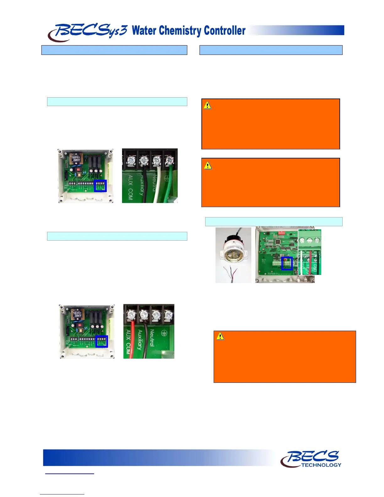
B – 10.1: Line Powered
Make sure the hat jumper is in the lower position
“L”. The black wire goes into the position labeled
Auxiliary, the white wire goes into the Neutral
position next to that, and the green wire goes into
Earth Ground position next to that. Nothing
should be connected to the AUX COM terminal.
NOTE: The black and white wires are colored
brown and blue outside North America.
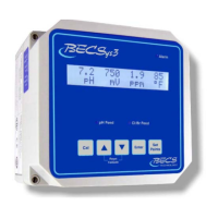
B – 10.2: Common Powered
Connect the incoming power to the AUX COM
terminal (the red wire shown below) and move the
hat jumper for the Aux relay to the upper position
“C”. The black wire goes into the position labeled
Auxiliary. Leave the Neutral and Earth Ground
terminals unconnected inside the controller. The
Neutral and Earth Grounds from the feeder/device
must be connected to the Neutral and Earth
Ground of the power source supplying this relay.
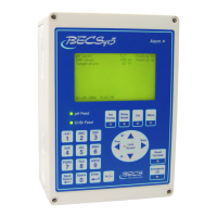
B – 11: Wiring a Flow Switch
A Flow Switch must be used in the operation of a
BECSys3 Controller.
A paddlewheel flow switch or reed flow switch is
incorporated into the flow cell to disable chemical
feed in the event of loss of flow.
B – 11.1: Paddlewheel Flow Switch
Connect the wires to CN5 in the cover of the unit.
The black wire goes to Ground, the white wire
goes to Flow, and the red wire goes to +12V.
With the paddlewheel flow switch, whenever the
wheel spins, the green “flow” light on the flow
switch will be on.
Warning: NEVER BYPASS FLOW
SWITCH CONNECTIONS
The Flow Switch is a critical safety device which
prevents uncontrolled chemical feed.
Uncontrolled feeding of chemicals can result in
injury or death.
Warning: Failure to incorporate a Flow
Switch and Flowcell into the sample
Stream of your BECSys chemical controller
can result in injury or death to swimmers in or
around the pool if the recirculation pump
should fail or shut down.
Warning: A check valve must be installed with
the paddlewheel flow switch to prevent backflow
when the system is shut down. If a check valve is
not installed, backflow could give the controller a
false reading of flow and continue to pump
chemicals into the pool.