Page 4
www.becs.com 9487 Dielman Rock Island Ind Dr, St. Louis, MO 63132
Installation and Technical Manual Rev: H10
S
S
e
e
c
c
t
t
i
i
o
o
n
n
A
A
:
:
M
M
o
o
u
u
n
n
t
t
i
i
n
n
g
g
t
t
h
h
e
e
B
B
E
E
C
C
S
S
y
y
s
s
3
3
C
C
o
o
n
n
t
t
r
r
o
o
l
l
l
l
e
e
r
r
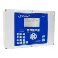
A – 1: Mounting the Controller
The BECSys3 Controller and flow cell are mounted
separately. The BECSys3 enclosure should be
mounted to the wall with four anchor bolts, one
installed in each corner of the enclosure base. To
mount the BECSys3 properly, please use the
included mounting template and hardware. Drill the
holes for the anchors using a 3/16” drill bit. Install
the anchors in the wall. Remove the lid from the
unit and place the included screws in the four
corners of the box. Attach the screws into the
anchors. The BECSys3 and flow cell should be
mounted in a location that is free from chemical
fumes and excessive heat, isolated from electrical
interference, and near a power source protected by a
ground fault interrupter. The BECSys3 has a
NEMA4 weather resistant enclosure but should still
be protected if mounted outdoors.
A – 2: Wrapping the Fittings
When assembling the flow cell, first open the bag of
flow cell fittings and wrap each fitting two times
around clockwise with Teflon tape.
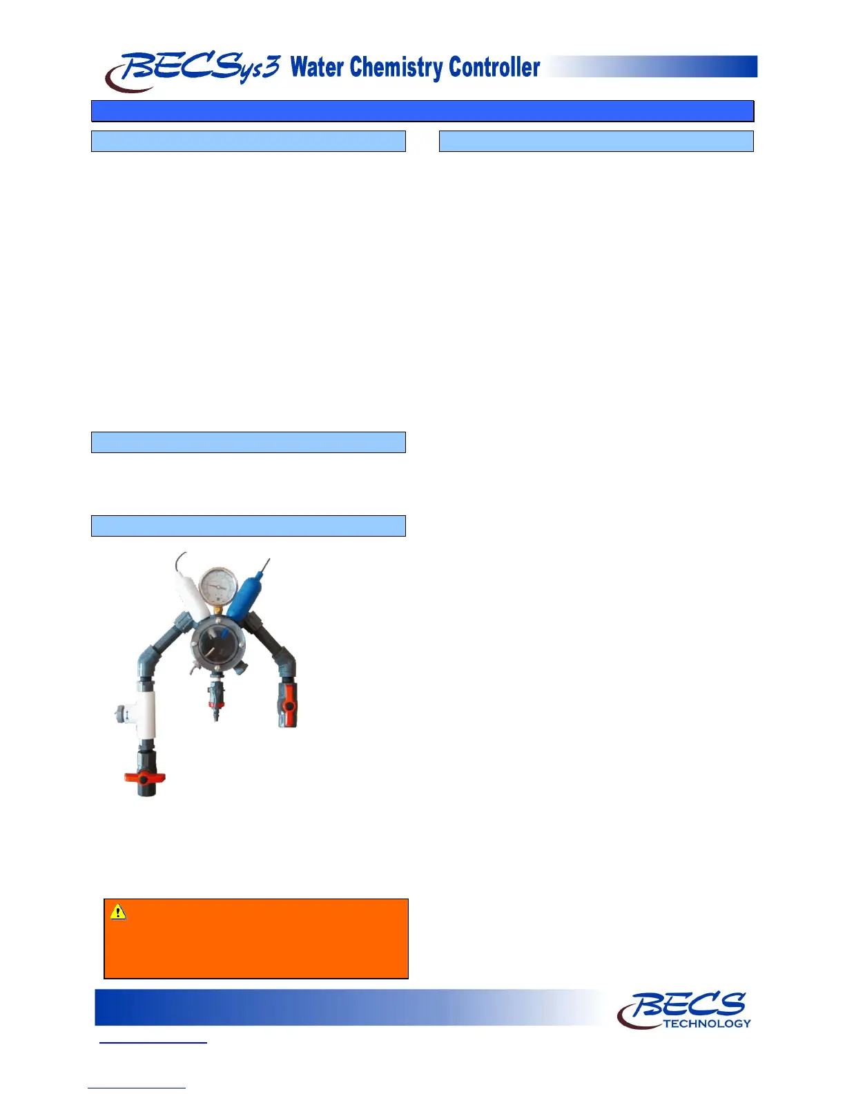
A – 3: Assembling the Flow cell
Assemble the flow cell as shown below:
When installing the pH or ORP (if included) sensors,
remove the wetting cap, and then remove any
existing Teflon tape from the sensor threads. Re-
wrap the threads with new Teflon tape. Rinse the
sensor tip in de-ionized water and install as shown.
A – 4: Plumbing the Sample Stream
Install the sample stream; ½-inch tubing is
recommended for sample stream pickup and return.
Make sure that you tap the supply off the
discharge side of the recirculation pump,
upstream
of the chemical injection points. The
sample should be filtered water. Connect the sample
stream pickup line to the flow cell and run the
sample stream return line from the flow cell to the
suction side of the main recirculation pump. Install
½-inch ball valves to allow isolation of the sample
lines.
Warning: These sensors should be hand-
tightened only. Tools are not necessary for
installing the pH or ORP sensor and will
damage the sensor housing.