GN-9371_2_3 User Manual
Page 99 of (110)
G-series GN-9371_2_3 PIO Rev. 1.02.docx
A.5 Example
A.5.1 Example of Input Process Image(Input Register) Map
Input image data depends on slot position and expansion slot data type. Input process image data is only
ordered by expansion slot position when input image mode is uncompressed (mode 0, 2). But, when input
image mode is compressed (mode 1, 3), input process image data is ordered by expansion slot position and
slot data type. Input process image mode can be set by special register 0x1114(4372). Refer to 6.3.3.
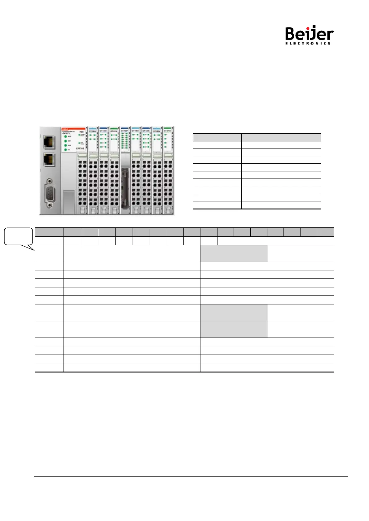
• For example slot configuration
• Input Process Image Mode#0 (Status(1word) + Uncompressed Input Processing Data)
0x0001 Discrete In 8pts (Slot#2) Empty, Always 0
Discrete In 4pts
(Slot#1)
Analog Input Ch0 high byte (Slot#3)
Analog Input Ch0 low byte (Slot#3)
Analog Input Ch1 high byte (Slot#3)
Analog Input Ch1 low byte (Slot#3)
Analog Input Ch2 high byte (Slot#3)
Analog Input Ch2 low byte (Slot#3)
Analog Input Ch3 high byte (Slot#3)
Analog Input Ch3 low byte (Slot#3)
Discrete In high 8pts (Slot#4)
Discrete In low 8pts (Slot#4)
0x0007 Discrete In 8pts (Slot#6) Empty, Always 0
(Slot#5)
0x0008 Analog Input Ch0 low byte (Slot#8) Empty, Always 0
(Slot#7)
Analog Input Ch1 low byte (Slot#8)
Analog Input Ch0 high byte (Slot#8)
Analog Input Ch2 low byte (Slot#8)
Analog Input Ch1 high byte (Slot#8)
Analog Input Ch3 low byte (Slot#8)
Analog Input Ch2 high byte (Slot#8)
Analog Input Ch3 high byte (Slot#8)
Expansion Module Status :
0: Normal Operation 1: Internal protocol Standby
2: Internal protocol Communication Fault 3: Slot Configuration Failed
4: No Expansion Slot
FP (Field Power) :
0: 24Vdc Field Power On. 1: 24Vdc Field Power Off
EW (MODBUS Error Watchdog) :
0: No Error Watchdog 1: Error Watchdog once more since its last restart, clear counters operation, or power-up.


 To Next Page