TM 55-1520-228-BD
ELECTRICAL AND AVIONICS SYSTEM
MATERIALS/TOOLS REQUIRED:
Replacement Segment (item 10, Appx B)
Stripper or Knife
Splice (item 10, Appx B)
Insulation Sleeve (item 10, Appx B)
Crimp Tool
PROCEDURAL STEPS:
1.
Cut out damaged cable (up to 9
inches in length).
2.
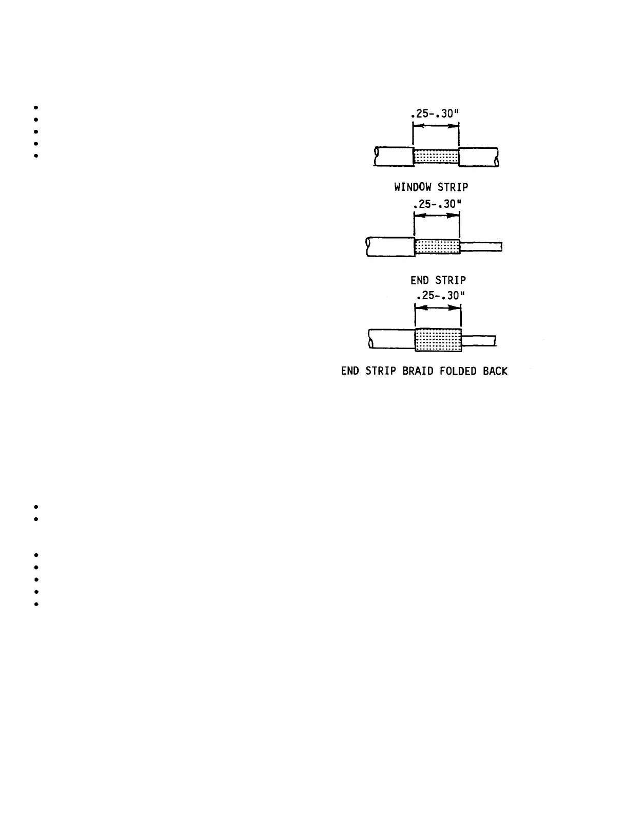
Prepare cable for splice. Refer to
Figure 11-12 and Table 11-5.
3.
Use one of the options of paragraph
11-5 to splice the ends of the replace-
ment segment onto the damaged cable.
4.
Record BDAR action taken. When
mission is complete, as soon as
practical, repair the equipment/system
using standard maintenance procedures.
11-10. SHIELD TERMINATORS.
GENERAL INFORMATION: The kit contains
various types of shield terminators for
shielded cable.
LIMITATIONS:
This is a temporary
repair.
PERSONNEL/TIME REQUIRED:
1 Soldier
15 Minutes
MATERIALS/TOOLS REQUIRED:
Shield Terminator (item 10, Appx B)
Reflector
Heat Gun/Heat Source
Stripper or Knife
Insulating Sleeve (item 10, Appx B)
PROCEDURAL STEPS:
1.
Prepare cable
Figure 11-18.
for repair. Refer to
Figure 11-18.
Shield Terminator
Repair Preparation
2.
Position shield terminator on cable
as shown in Figure 11-19. (Select the
smallest terminator that slides easily
over the prepared cable.)
3.
Heat shield terminator until solder
melts and flows into wire strands, red
color disappears, and seals melt and
flow at both ends.
Use reflector with
shield terminator of wire repair kit
with temperature set at 900°F.
4.
Terminate the ground lead as
directed in aircraft wiring manual.
5.
Record BDAR action taken. When
mission is complete, as soon as
practical, repair the equipment/system
using standard maintenance procedures.
11-24