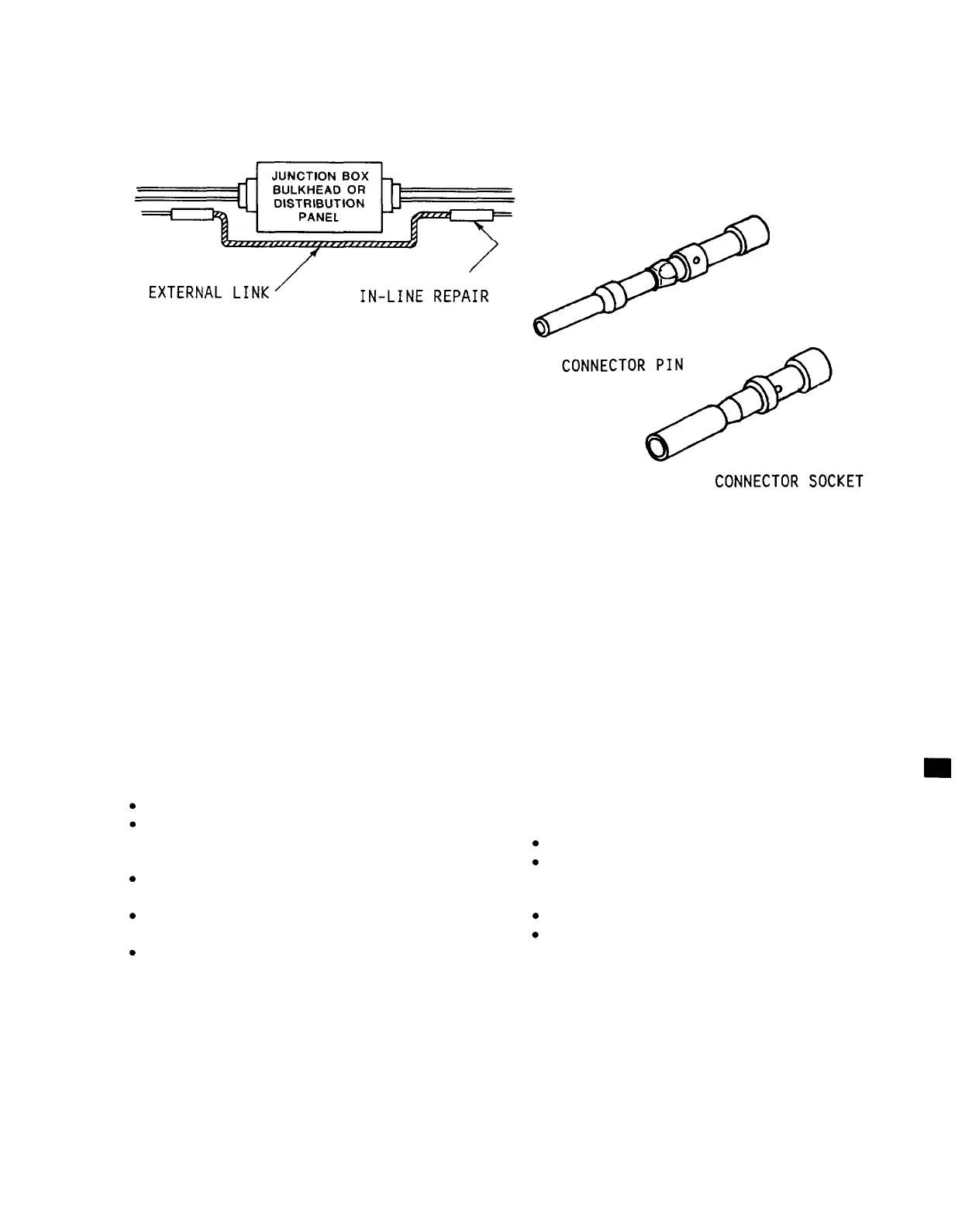
Figure 11-32.
11-20.
CONNECTOR
Component Bypass
REPAIR.
GENERAL INFORMATION: Deformed, crushed,
missing, or otherwise damaged connectors
can be replaced or repaired.
If a
replacement connector is not available
to replace a crushed connector, clean up
fragments of the connector and use
jumper wires to bridge wire ends
together.
If only part of the connector
has been damaged and there are unused
pins/sockets on the connector which are
undamaged, wires on both sides of the
connectors can be moved to the unused
good pins/sockets.
Also, any available
undamaged pigtails on the connector may
be used.
OPTION 1:
Damaged Pins or Sockets; No
Damage to Connector.
LIMITATIONS: None.
PERSONNEL/TIME REQUIRED:
1 Soldier
10 Minutes Per Wire
MATERIALS/TOOLS REQUIRED:
Replacement Pins/Sockets
(item 2, Appx B)
Insertion/Extraction Tool
(item 2, Appx B)
Knife
PROCEDURAL STEPS:
1.
Solder or crimp wires to
pin/sockets, Figure 11-33.
2.
Insert the pins/sockets into the
connector.
TM 55-1520-228-BD
ELECTRICAL AND AVIONICS SYSTEM
3.
Record BDAR action taken. When
mission is complete, as soon as
practical, repair the equipment/system
using standard maintenance procedures.
Figure 11-33. Connector Pin and Socket
NOTE
Superglue or epoxy may be used to
secure the original or replace-
ment pin back into place.
Avoid
getting glue or epoxy on contact
surface of pin.
OPTION 2: Bridge Across Partially or
Fully Damaged Connector.
LIMITATIONS: Temporary repair.
PERSONNEL/TIME REQUIRED:
1 Soldier
10 Minutes Per Wire
MATERIALS/TOOLS REQUIRED:
Wire Splice (item 10, Appx B)
Wire (items 61, 62, Appx C)
PROCEDURAL STEPS:
1.
Locate the damaged wire ends that go
into connector.
2.
Splice the appropriate wires
together.
The splice will bypass the
connector.
11-33