TM 55-1520-228-BD
ELECTRICAL AND AVIONICS SYSTEM
LIMITATIONS:
Some loss of battery
voltage (1.25 to 1.50 V dc per cell
removed) and amperage capacity.
PERSONNEL/TIME REQUIRED:
. 1 Soldier
. 30 Minutes
MATERIALS/TOOLS REQUIRED:
. 1 Multimeter with Leads
(item 9, Appx B)
. Rubber Gloves
. Protective Goggles
. Rubber Apron
. Torque Wrench
. One Foot No. 4 AWG Wire or
Equivalent
PROCEDURAL STEPS:
1.
Disconnect battery and remove from
aircraft if necessary.
2.
Release snap fasteners and remove
cover.
3.
Use a multimeter to measure voltage
across each cell.
Normal readings
should be 1.25 to 1.5 V dc per cell.
Remove cells that are dead.
For engine
cranking loads, cell voltages as low as
0.6 V dc are acceptable. Also, remove
any damaged, cracked, or extremely hot
cells leaking or spewing electrolyte.
WARNING
Be extremely careful when
removing or installing battery
cells.
Bodily injury and equip-
ment damage may result if any
metal tools or parts accidentally
cause a short circuit.
4.
To remove bad cells, use a 3/8 inch
socket or equivalent to loosen and
remove terminal screws. Remove washers
and terminal links.
To remove indivi-
dual cells, screw terminal screws back
into each cell terminal, grasp these
screws with pliers and lift the cell
straight up.
5. After removing bad cells, prepare
jumper from 1 foot of No. 4 AWG and two
terminal lugs.
Remove 1/2 inch of insu-
lation from one end of wire and crimp
terminal lug on stripped end of wire.
Measure and cut wire to needed length,
strip 1/2 inch of insulation, and crimp
terminal lug to other end of wire.
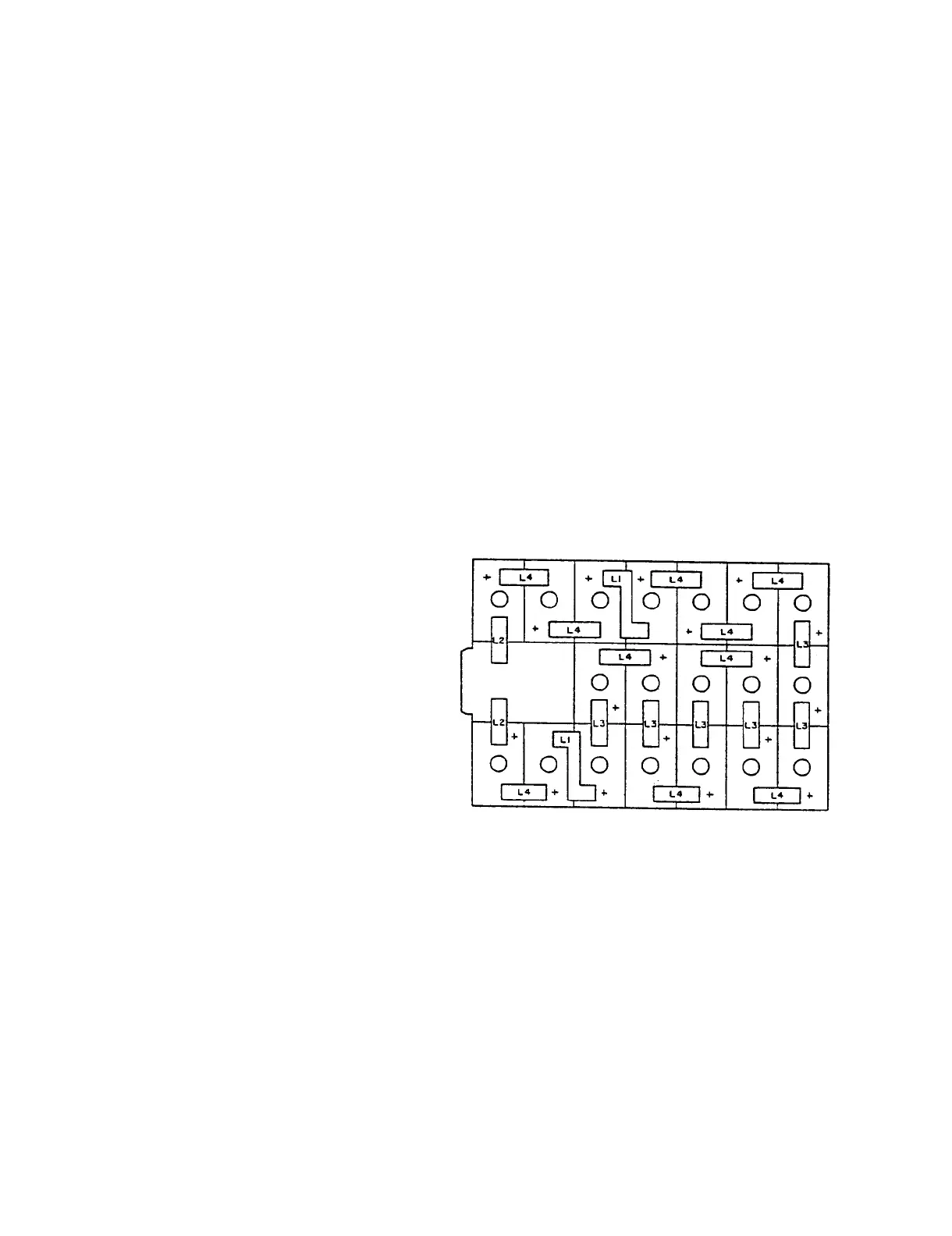
6.
Install jumper across removed cells
in place of terminal links. Cells are
connected in series (positive to
negative), Figure 11-40.
7.
Torque terminal screws to between 35
and 50 inch-pounds.
If torque wrench is
not available, tighten firmly with
wrench or pliers.
8.
Replace cover and install battery in
aircraft.
Figure 11-40.
Battery, Storage
BB-476/A, Cell Layout
11-40
 Loading...