TM 55-1520-228-BD
ELECTRICAL AND AVIONICS SYSTEM
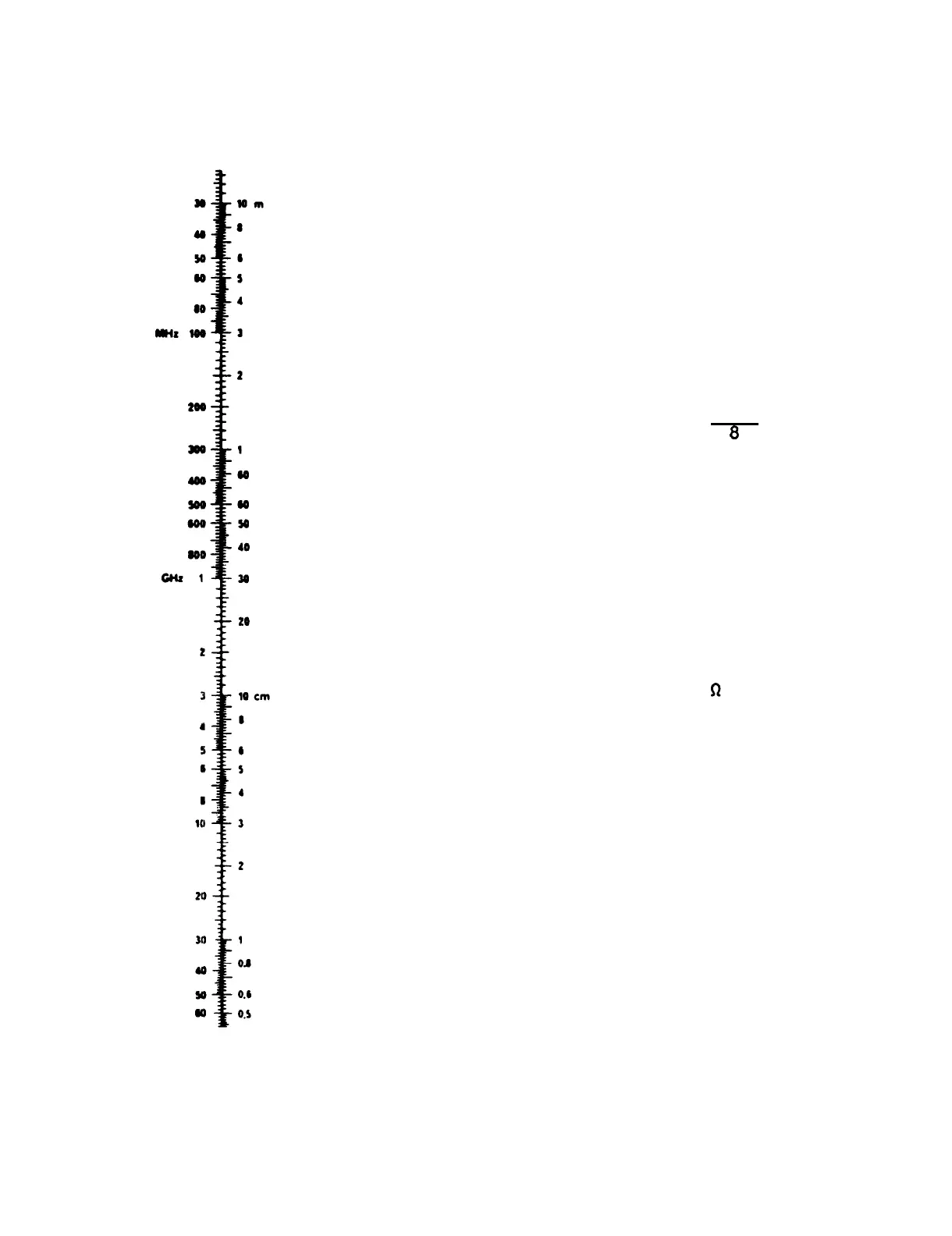
Frequency Wavelength
Figure 11-45. Frequency vs. Wave Length
TO CHANGE
MULTIPLY BY
Centimeters . . Inches. . . . . . 0.394
Meters. . . . . Feet. . . . . . . 3.280
11-46
●
FM radio with frequency range of 30 to
69.95 MHZ.
●
Center of frequency range is 50 MHZ.
●
Using Figure 11-45, look under frequency
column for 50 MHZ on the wave length
side of the Table, 6 M is shown.
●
Use Figure 11-45 to convert meters to
feet.
Six meters multiplied by 3.280
= 19.68 feet for one wave length.
●
Divide the one wave length by 8, for a
1/8 wave length antenna, 19.68 = 2.46
feet.
Multiply the 1/8 wave length by
a .95 correction factor: 2.46 ft. X
.95
= 2.34 feet.
This is the length
of the radiating element.
2. Cut the coax cable to the length of
the required radiating element. Remove
the outer insulation and shield from the
piece of coax cable and then strip a 1
inch piece of insulation from each end
exposing the center conductor, Figure
11-46A.
3. Wrap and solder the 52 resistor to
one end of the radiating element as per
Figure 11-46B.
This completes the fabri-
cation of the radiating element of the
antenna.
4.
Next, remove the structural panel on
the right-hand side just forward of the
tail boom, Figure 11-47, by removing
twenty-seven screws.
5.
At the tail boom quick disconnect,
locate coax cable marked 1 ARC 114-101B
and disconnect it. Remove the coax con-
nector and prepare a 4 inch pigtail ter-
mination on the end of the coax cable as
shown in Figure 11-46C.
6.
Stick the radiating element of the
antenna from step three with the resis-
tor end down into the drain hole in the
bottom of the tail boom where it joins the
fuselage, Figure 11-47.
 Loading...