TM 55-1520-228-BD
11-24. DAMAGED OR DEFECTIVE POWER RELAYS.
GENERAL INFORMATION: A power relay is
an electrically operated switch between
the main bus and other electrical com-
ponents in the aircraft. The relays are
normally controlled by a switch in the
cockpit.
Damage incurred to power
relays may be temporarily fixed by one
of two options.
a. First option:
Replace with good
relay salvaged from non-flyable aircraft
or a nonessential circuit.
b.
Second option: Jumper across
power terminal and bus bar terminal
studs located on relay case.
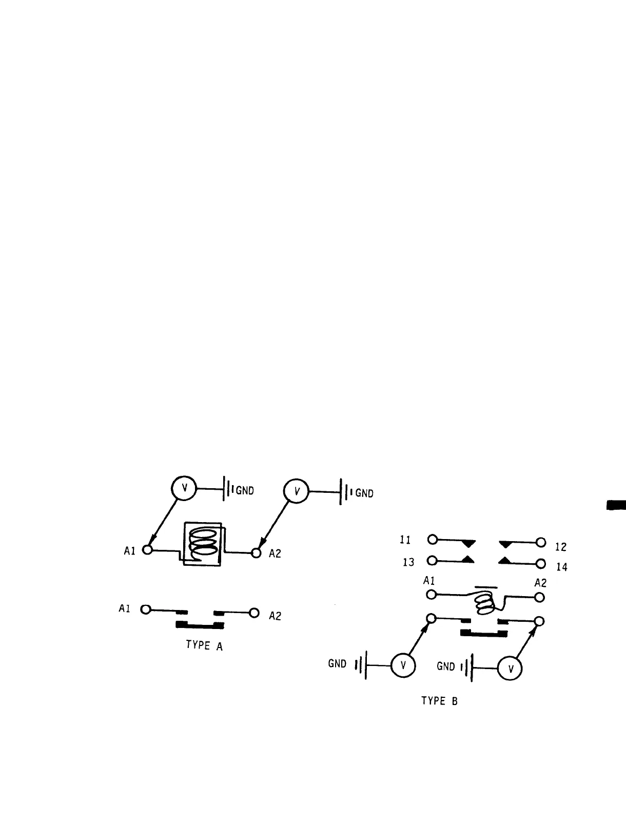
To check
power relay for malfunction, locate ter-
minals X1 and X2 on the relay.
With a
multimeter set on the 0-50 V dc scale,
check the voltage from terminals Xl and
X2 to the aircraft fuselage (ground),
Figure 11-41. One of the two terminals
should have 24-28 V dc on it when the
power relay control circuit is
energized.
No dc voltage indicates
ELECTRICAL AND AVIONICS SYSTEM
damage to the control circuit wiring.
Repair control circuit wiring. With
24-28 V dc applied to terminals X1 or
X2 of the power relay, check the voltage
between terminals A1, A2, and the
aircraft fuselage (ground), Figure
11-41.
The voltage on terminals A1 and
A2 should be identical. If there is no
voltage on either one of the two ter-
minals A1 or A2 with the relay
energized, the relay should be considered
defective and replaced.
OPTION 1:
Salvaged Power Relay
Replacement.
NOTE
Identical part number (Figures
11-42) denotes interchangeability.
If damage is extensive, salvaged
relays may be difficult to attach
to bulkheads.
Figure 11-41.
Block Diagram Power Relay, Check and Test
11-41
 Loading...