TM 55-1520-228-BD
ELECTRICAL AND AVIONICS SYSTEM
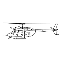
Figure 11-27.
Coax Splice Inner Sleeve
Figure 11-28.
Coax Splice Shield Sleeve
PROCEDURAL STEPS:
1.
Prepare coax cable, Figure 11-26.
Refer to Table 11-5.
2. Slide the tubing, inner sleeve, and
filler sleeve onto one of the coax
cables in the order given.
3.
Splice the center conductor. Use
the red cavity of the crimp tool.
4.
Shrink the filler sleeve over the
splice.
Use reflector, temperature set
at 900°F. Keep hot air away from shield
sleeve and tubing.
5.
Center and shrink the shield sleeve
over the splice area so that the solder
melts and flows, Figure 11-29. Shield
sleeve must overlap coax braid at both
ends. Use same reflector and tem-
perature.
Keep hot air away from
tubing.
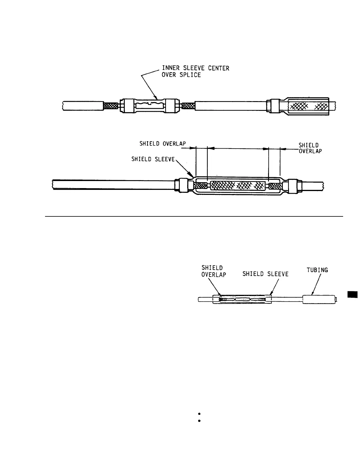
6.
Center and shrink the tubing over
the splice area. Use reflector with
temperature set at 900°F.
7.
Record BDAR action taken. When
mission is complete, as soon as
practical, repair the equipment/system
using standard maintenance procedures.
Figure 11-29. Coax Splice with
Tubing Sleeve
11-18. COAX SPLICE FOR RG-58C/U,
RG-233/U, RG-59B/U, AND RG-71B/U.
GENERAL INFORMATION: There are various
coax splices in the wiring repair kit
that may be used for the different
types and sizes of coax cable.
LIMITATIONS: This is a temporary repair.
PERSONNEL/TIME REQUIRED:
1 Soldier
15 Minutes
11-31