Function
16
TGH1361en/11.2009
sulation monitoring is started.
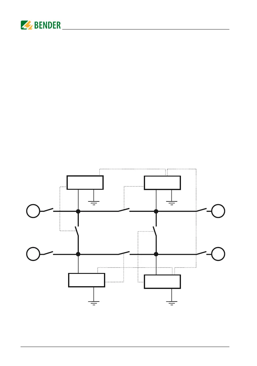
With this function, selective disconnection of an IRDH275 in interconnected
IT systems can be carried out via auxiliary contacts of the respective coupling
switch. One coupling switch each in a line-type or ring-type arrangement can
deactivate a subsequent IRDH275. This arrangement guarantees that only
one A-ISOMETER® is active in each galvanically connected system. In a ring-
type arrangement with all coupling switches closed, it can be assumed that
all A-ISOMETER®s are deactivated. In order to prevent this, a BMS Master
(IRDH275B BMS address 1) monitors the condition of the function input F1/
F2 of all slave A-ISOMETERs®. When all slave A-ISOMETERs® are in the
STANDBY mode, the insulation monitoring function of the Master
A-ISOMETER® and hence the function input F1/F2 of the Master are without
function in this mode.
Details are shown in the graphic below.
BMS bus (A/B, RS485)
F1/F2
PE PE
PE PE
IT system 1 IT system 2
IT system 3IT system 4
G
G
G
G
Addr. 1
Addr. 2
Addr. 4
Addr. 3
IRDH275B
IRDH275B
IRDH275B
IRDH275B
F1/F2
F1/F2
F1/F2
 Loading...


