Connection
25
TGH1361en/11.2009
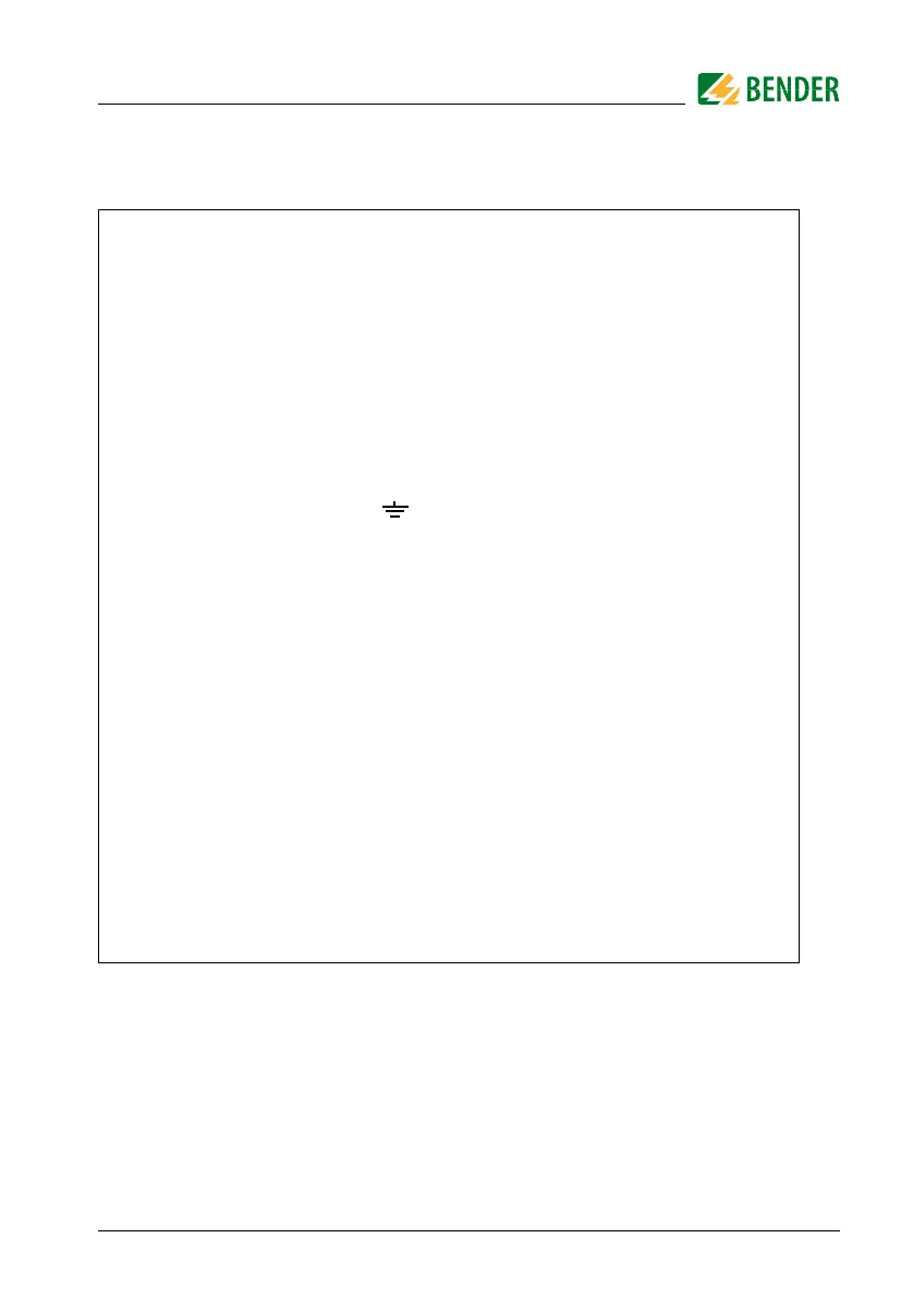
Legend to wiring diagram:
1 Supply voltage U
s
(see nameplate) via 6 A fuse
2, 3 Connection to the 3AC system to be monitored:
connect terminals L1, L2 to neutral conductor N or
terminals L1, L2 to conductor L1, L2
4 Connection to the AC system to be monitored:
connect terminals L1, L2 to conductor L1, L2
5 Connection to the DC system to be monitored:
connect terminal L1 to conductor L+, terminal L2 to conductor L-
6 Separate connection of and KE to PE
7 External TEST button (NO contact)
8 External RESET button (NC contact or wire jumper),
when the terminals are open, the fault message will not be stored
9 STANDBY by means of the function input F1, F2:
When the contact is closed, insulation measurement does not take
place;
system disconnection
10 IRDH275: current output, galvanically separated: 0...400 μA
IRDH275B: current output, galvanically separated:
0...20 mA or 4...20 mA
11 Serial interface RS485 (termination 120 Ω resistor)
12 Alarm relay 1; changeover contacts provided
13 Alarm relay 2; (device fault relay) changeover contacts provided
 Loading...


