Function
19
IRDH275BM-7_D00123_06_M_XXEN/07.2018
3.2 Product description
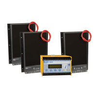
The ISOMETER® IRDH275BM-7 and coupling device AGH675S-7 moni-
tor the insulation resistance of IT medium voltage systems up to 7.2 kV.
The ISOMETER® IRDH275BM-7 and two coupling devices AGH675S-
7MV15 monitor the insulation resistance of IT medium voltage systems
up to 15.5 kV.
Both combinations are suitable for universal use in 3/(N) AC, AC/DC and DC
systems. AC systems may include extensive DC supplied loads, such as con-
verters or thyristor-controlled DC drives. Drive systems including a converter
and a motor in medium voltage systems can be monitored.
When the AGH675S-7 is connected in the mid-point of the converter
DC intermediate circuit, a maximum of ±7.2 kV against PE may occur.
When the two coupling devices AGH675S-7MV15 are connected in the
mid-point of the converter DC intermediate circuit, a maximum of
±15.5 kV against PE may occur.
The device automatically adapts itself to the existing system leakage capaci-
tance. The IRDH275BM-7 can be used in combination with a control and indi-
cation panel, e.g. PRC1470 version 2 or higher, on the BMS (BMS = Bender
Measuring Device Interface) bus.
3.3 Function
The combination ISOMETER® IRDH275BM-7 and coupling device AGH675S-7
or two coupling devices AGH675S-7MV15 is operated between the unearthed
system (IT system) and the protective conductor (PE).
The response values and other function parameters are set via the function
keys. The parameters are indicated on the LC display and are stored in a non-
volatile memory (EEPROM) after the setting is completed.
A microprocessor-controlled pulsating AC measuring voltage is superim-
posed on the IT system to be monitored ( measuring principle*).
The measuring cycle consists of positive and negative pulses of the same am-
plitude. The period of these pulses depends on the respective system leakage
capacitances and the insulation resistances of the IT system to be monitored.