BENNING IT 115 Device description
- 28 -
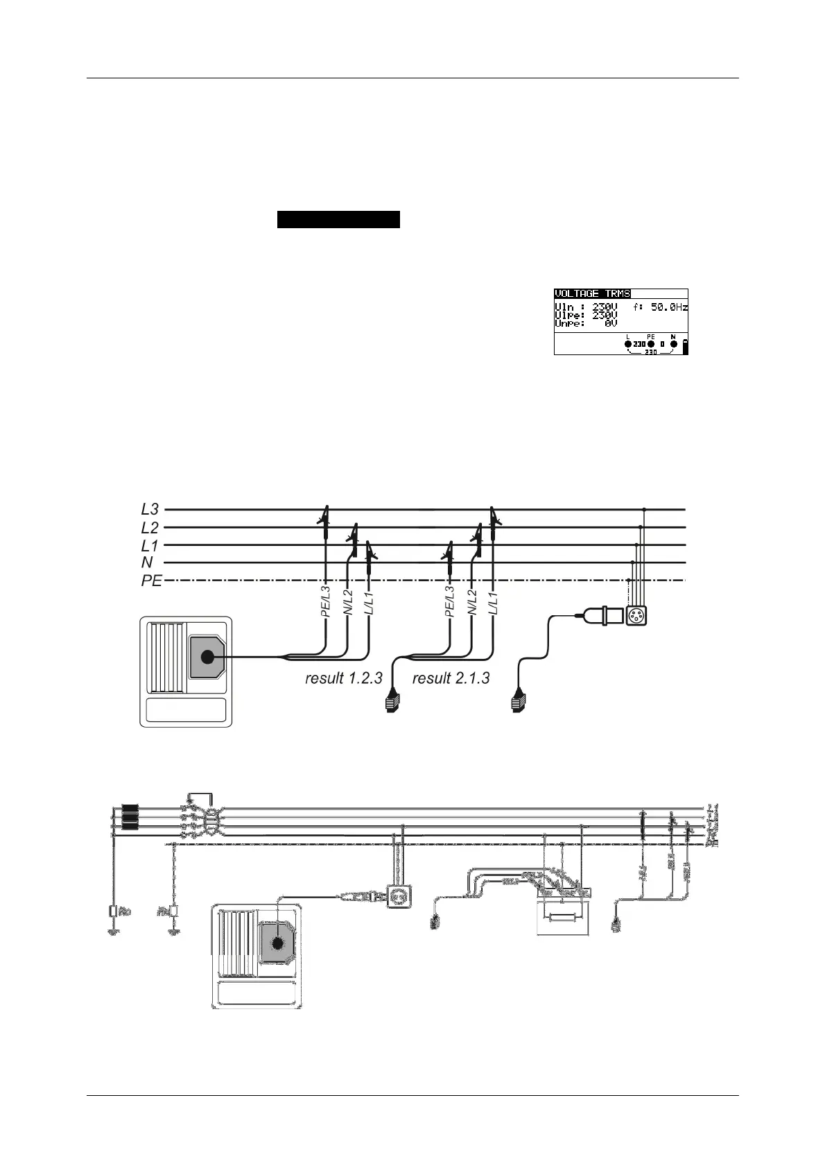
5 Measurements
5.1 TRMS voltage, frequency and phase sequence
The voltages applied to the testing terminals are permanently displayed by means of the
connection monitor. In the VOLTAGE TRMS measuring range (true RMS voltage value), the
measured values for voltage (AC/DC) and frequency as well as the phase sequence (rotary
field) detected can be saved. The measurements are carried out in compliance with the
EN 61557-7 standard.
Key function as described in chapter
4.2 Function selector switch
Figure 5.1:
Voltage in a single-phase system
Testing parameters
It is not necessary to set any parameters.
Connection plan
Figure 5.2: Connection of the three-wire test cable and the
optional CEE measuring adapter (044148) in a three-phase system
Figure 5.3: Connection of the optional "Commander" test plug (044149) and the three-wire test
cable in a single-phase / three-phase system