BENNING IT 115 Device description
- 44 -
5.6.1 Line impedance and prospective short-circuit current
Connection plan
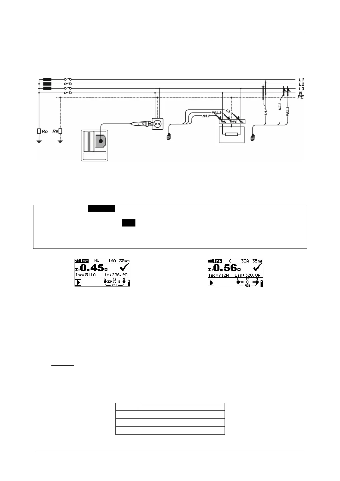
Figure 5.28: Connection of the optional "Commander" test plug (044149)
and the three-wire test cable
How to perform line impedance measurements
Select the Z
I
(L-N/L) [English: Z
LINE
(L-N/L)] function by means of the function selector
switch.
Set the sub-function to Zline.
Set the testing parameters.
Connect the test cables to the test object (see figure 5.28).
Press the "TEST" key to start the measurement.
x
Figure 5.29: Example of a line impedance measurement
Results displayed:
Z ............... line impedance
Isc ............ prospective short-circuit current
Lim ........... lower limit of the prospective short-circuit current
The prospective short-circuit current is calculated as follows:
Z
kUn
I
SC
SC
with:
Un .......nominal voltage L-N or L1-L2 (see table below),
ksc ......correction factor for short-circuit current Isc (see chapter 4.4.6 Isc factor (scaling factor))
U
Voltage range (L-N or L1-L2)
110 V
(93 V U
134 V)
230 V
(185 V U
266 V)
400 V
(321 V U
485 V)