BENNING IT 115 Device description
- 41 -
5.5 Loop impedance and prospective short-circuit current
The loop impedance is a complex AC current resistance within a fault loop (earth fault L-PE)
consisting of current source, external conductor and protective conductor. The installation tester
measures the impedance of the loop and calculates the short-circuit current. The measurement
complies with the requirements specified in the EN 61557-3 standard.
Key function as described in chapter
4.2 Function selector switch
Figure 5.23:
Loop impedance
Testing parameters
Selects the loop impedance sub-function [Zloop, Zsrcd]
Selects the fuse type [---, gL/gG, B, C, K, D]
Nominal current
of the fuse
Maximum tripping time of the fuse
value)
Lower limit of the prospective short-circuit current
See Appendix A "Fuse table".
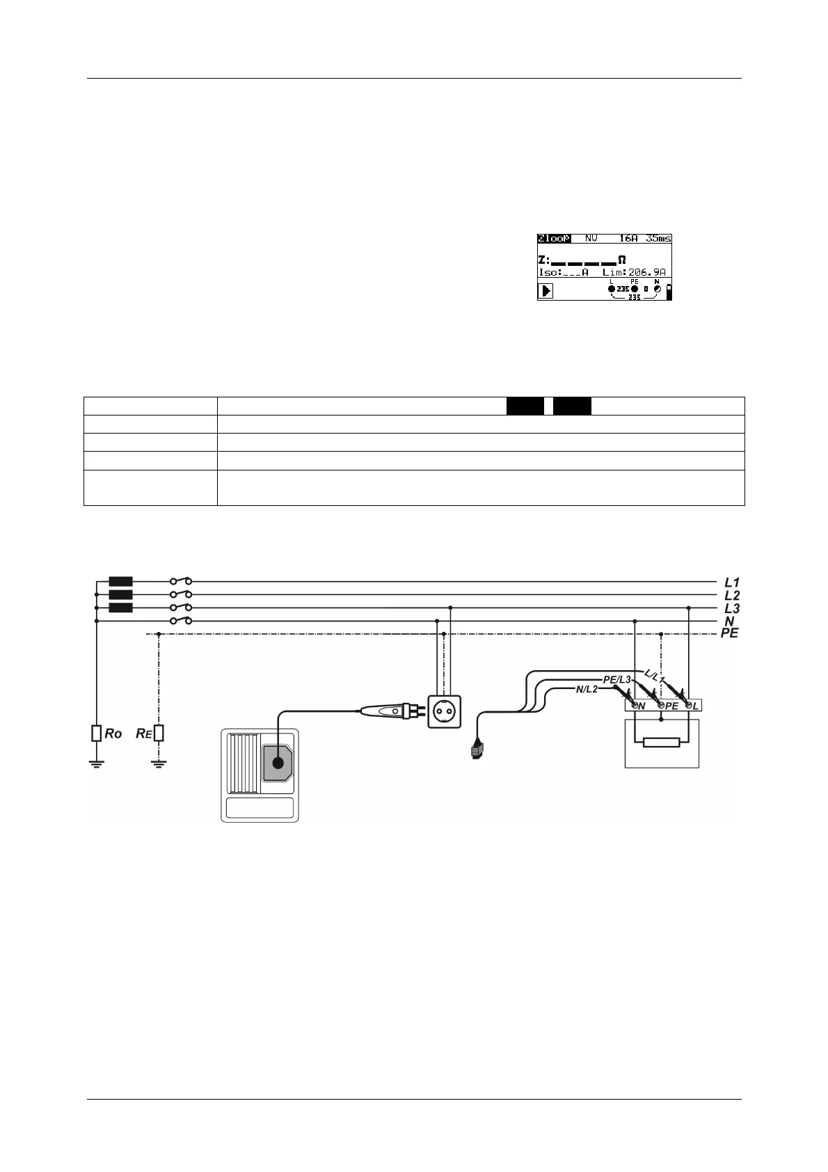
Connection plan
Figure 5.24: Connection of the optional "Commander" test plug (044149)
and the three-wire test cable