BENNING IT 115 Device description
- 39 -
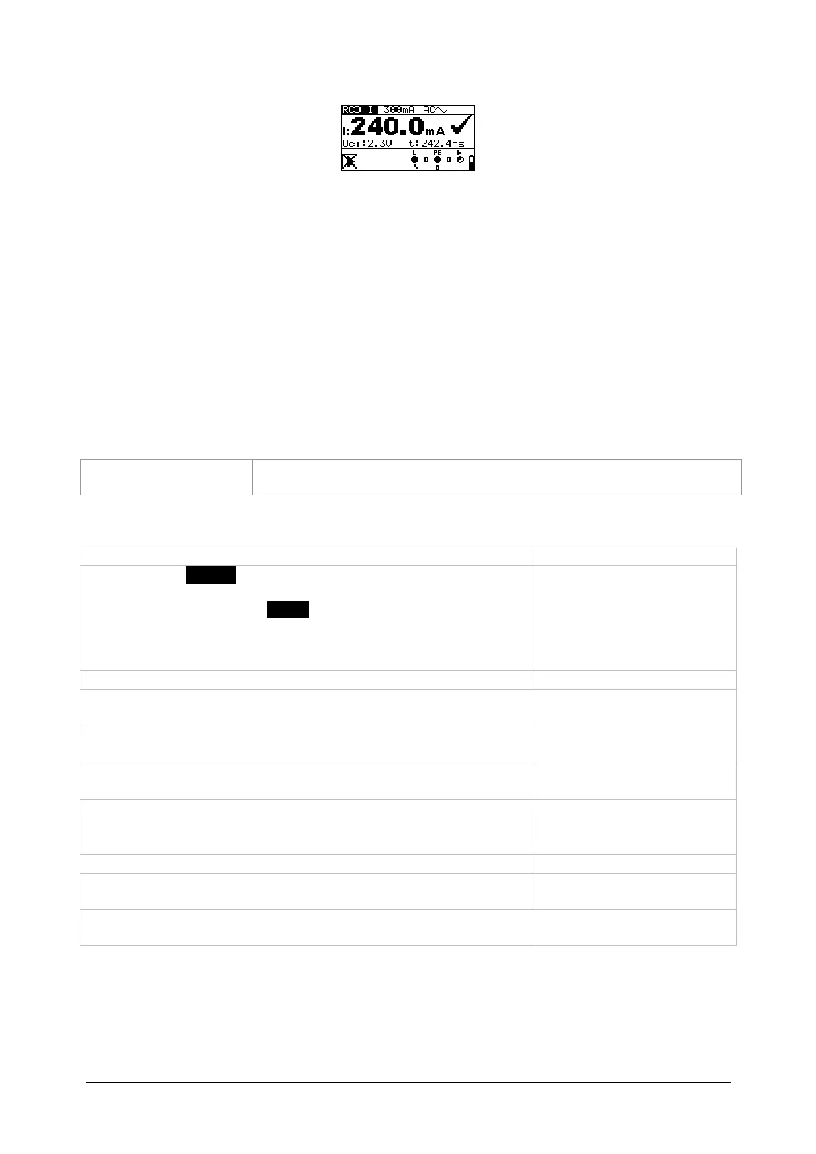
Figure 5.20: Example of a tripping current measurement
Results displayed:
I ........... tripping current
Uci ....... contact voltage at tripping current I or final value, if RCD does not trip
t ............ tripping time
5.4.4 Automatic test
The automatic RCD test is intended to perform a complete RCD test (tripping time at different
fault currents, tripping current and contact voltage) in a sequence of automatic tests controlled
by the installation tester.
Additional key
As soon as measurement is finished, the "
" key toggles between
the upper and lower part of the result field.
How to perform an automatic test
Steps of the automatic test
Select the FI/RCD function by means of the function selector
switch.
Set the sub-function to AUTO.
Set the testing parameters.
Connect the test cables to the test object (see figure 5.17).
Press the "
" key to start the measurement.
Start of test
Testing with I
N, 0 (step 1)
RCD should trip
Activating the RCD
Testing with I
N, 180 (step 2)
RCD should trip
Activating the RCD
Testing with 5I
N, 0 (step 3)
RCD should trip
Activating the RCD
Testing with 5I
N, 180 (step 4)
RCD should trip
Activating the RCD
Testing with ½I
N, 0 (step 5)
RCD must not trip
Testing with ½I
N, 180 (step 6)
RCD must not trip
Tripping current test, 0 (step 7)
RCD should trip
Activating the RCD
Tripping current test, 180 (step 8)
RCD should trip
Activating the RCD
End of test