BENNING IT 115 Technical data
- 58 -
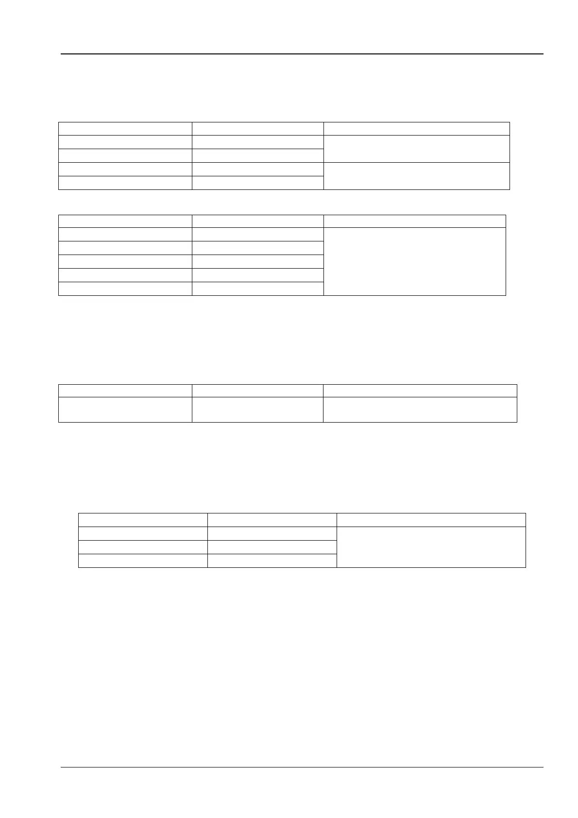
7.5 Line impedance and prospective short-circuit current / voltage drop
Line impedance
Measuring range according to EN 61557-3: 0.25 9.99 k
Measuring range (
) Resolution (
)
0.00 9.99
0.01
(5 % of the measured value + 5
digits)
10.0 99.9
0.1
100 999
1
10 % of the measured value
1.00 k 9.99 k
10
Prospective short-circuit current (calculated value)
0.00 0.99
0.01
Please observe the accuracy of the
line impedance measurement.
1.0 99.9
0.1
100 999
1
1.00 k 99.99 k
10
100 k 199 k
1000
Testing current (at 230 V) ...................... 6.5 A (10 ms)
Nominal voltage range ........................... 93 V 134 V (45 Hz 65 Hz)
185 V 266 V (45 Hz 65 Hz)
321 V 485 V (45 Hz 65 Hz)
Voltage drop (calculated value)
0.0 99.9
0.1
Please observe the accuracy of the line
impedance measurement*.
Z
REF
measuring range ............................ 0.00 Ω 20.0 Ω
* Please refer to chapter 5.6.2 Voltage drop for information on how to calculate the voltage drop.
7.6 Earthing resistance
Measuring range according to EN61557-5: 2,00 1999
Measuring range (
) Resolution (
)
0.00 19.99
0.01
(5 % of the measured value + 5 digits) 20.0 199.9
0.1
200 9999
1
Maximum auxiliary earth electrode resistance R
C
...100R
E
or 50 k (the lower value shall apply)
Maximum probe resistance R
P
................................100R
E
or 50 k (the lower value shall apply)
Additional error at R
Cmax
or R
Pmax
.............................(10 % of the measured value + 10 digits)
Additional error at interference voltage of 3 V (50 Hz) (5 % of the measured value + 10 digits)
Open-circuit voltage ................................................< 30 VAC
Short-circuit current ................................................<30 mA
Frequency of testing voltage ...................................125 Hz, sinusoidal
Interference voltage indicating threshold .................1 V (< 50 , maximum)
Automatic measurement of auxiliary earth electrode resistance and probe resistance.
Automatic monitoring of interference voltage.