BENNING IT 115 Device description
- 37 -
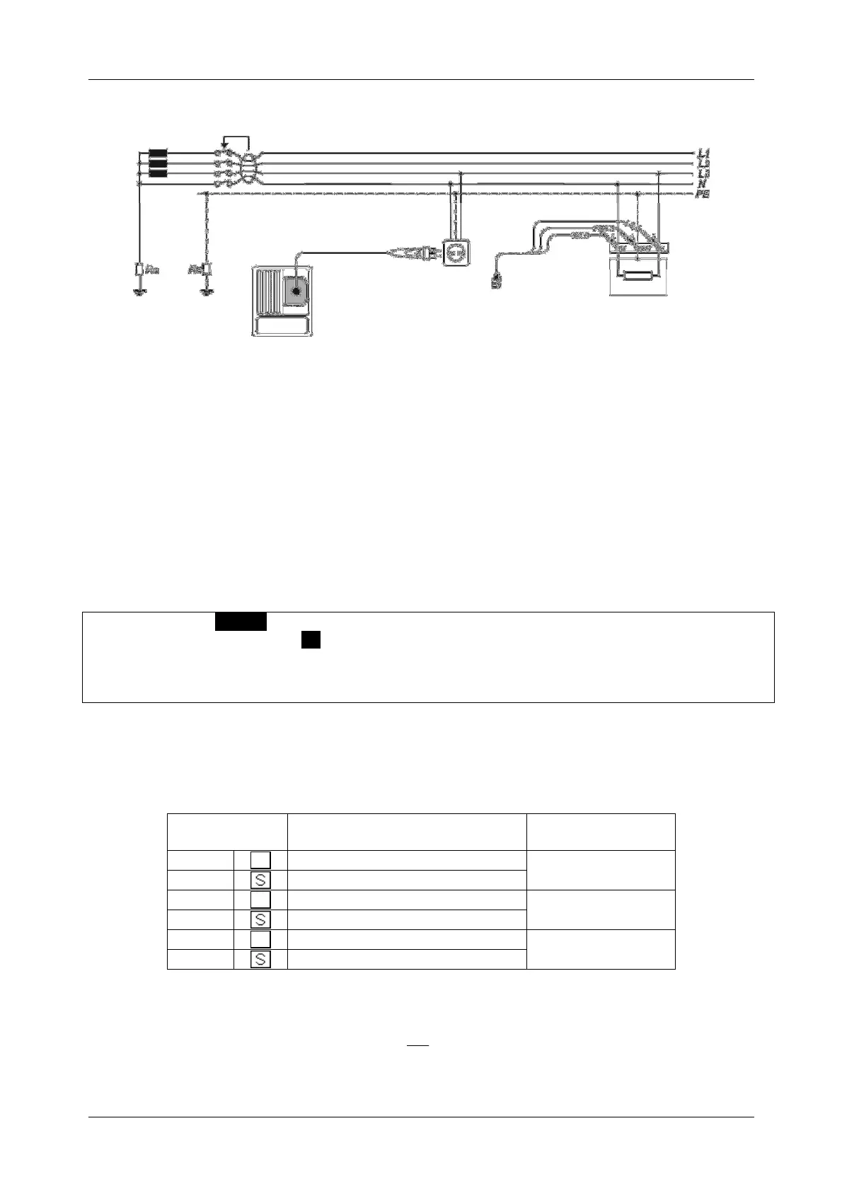
Connection plan
Figure 5.17: Connection of the optional "Commander" test plug (044149)
and the three-wire test cable
5.4.1 Contact voltage (Uc)
Leakage current flowing to earth via the protective conductor connection causes a voltage drop
at the earthing resistance, i.e. a voltage difference between the PE equipotential bonding and
earth. This voltage difference is called contact voltage and is applied to all accessible
conductive parts connected to protective earth (PE). The contact voltage always should be
lower than the maximum admissible contact voltage. Contact voltage is measured with a testing
current lower than ½ I
N
in order to avoid tripping of the RCD and then to be normalized to the
nominal value I
∆N
.
How to perform contact voltage measurements
Select the FI/RCD function by means of the function selector switch.
Set the sub-function to Uc.
Set the testing parameters.
Connect the test cables to the test object (see figure 5.17).
Press the "TEST" key to start the measurement.
The contact voltage displayed refers to the rated differential current of the RCD and is
multiplied with an appropriate factor for safety reasons.
The factor 1.05 is applied in order to
avoid a negative tolerance of the result.
Table 5.1 describes how the contact voltage is
calculated.
RCD type
proportional to
Nominal value I
N
AC
1.05I
any
AC
21.05I
N
A, F
1.41.05I
30 mA
A, F
21.41.05I
N
A, F
21.05I
<30 mA
A, F
221.05I
N
Table 5.1: Relation between Uc and I
N
The loop resistance is a purely indicative value and is calculated from the contact voltage
(without additional proportional factors).
N
C
L
I
U
R
.