BENNING IT 115 Device description
- 38 -
Figure 5.18: Example of a contact voltage measurement
Results displayed:
Uc ........ contact voltage
RL ........ loop resistance (fault loop resistance)
5.4.2 Tripping time (RCDt)
The tripping time measurement serves to test the sensitivity of the residual current protection
devices (RCDs) at different nominal tripping differential currents I
N
.
How to perform tripping time measurements
Select the FI/RCD function by means of the function selector switch.
Set the sub-function to RCDt.
Set the testing parameters.
Connect the test cables to the test object (see figure 5.17).
Press the "TEST" key to start the measurement.
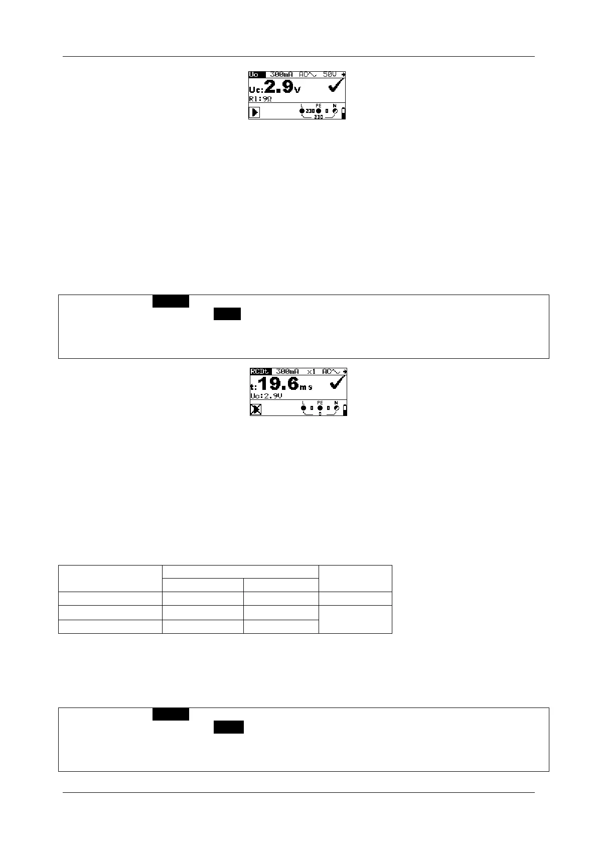
Figure 5.19: Example of a tripping time measurement
Result displayed:
t ............ tripping time
Uc ........ contact Voltage
5.4.3 Tripping current (RCD I)
For tripping current measurement, a continuously increasing fault current serves to determine
the limiting sensitivity for RCD tripping. The installation tester increases the fault current in small
steps within the whole range as follows:
RCD type
Curve
shape
0,2I
1,1I
sinusoidal
A, F (I
N
30 mA)
0,2I
N
1,5I
N
pulsating
A, F (I
= 10 mA)
0,2I
2,2I
The maximum testing current is I
(tripping current) or corresponds to the final value, if the RCD
does not trip.
How to perform tripping current measurements
Select the FI/RCD function by means of the function selector switch.
Set the sub-function to RCD I.
Set the testing parameters.
Connect the test cables to the test object (see figure 5.17).
Press the "TEST" key to start the measurement.