BENNING IT 115 Device description
- 46 -
Results displayed:
ΔU ............ voltage drop
Isc ............ prospective short-circuit current
Z ............... line impedance at the measuring point
Zref .......... line impedance at the reference point
The voltage drop is calculated as follows:
100
%
N
NREF
U
U
with:
ΔU ........ calculated voltage drop
Z ........... line impedance at the measuring point
Z
REF
...... line impedance at the reference point
I
N
.......... nominal current of the fuse
U
N
......... nominal voltage (see table below)
U
n
Voltage range (L-N or L1-L2)
110 V
(93 V U
134 V)
230 V
(185 V U
L-N
266 V)
400 V
(321 V U
485 V)
Notes:
If the reference impedance is not set, Z
REF
is assumed to be 0.00 Ω.
The Z
REF
value is deleted (set to 0.00 Ω) by pressing the "CAL" key, if the installation
tester is not connected to a voltage source.
The I
SC
value is calculated as described in chapter 5.6.1 "Line impedance and
prospective short-circuit current".
If the voltage measured is outside the ranges listed in the table above, the ΔU value will
not be calculated.
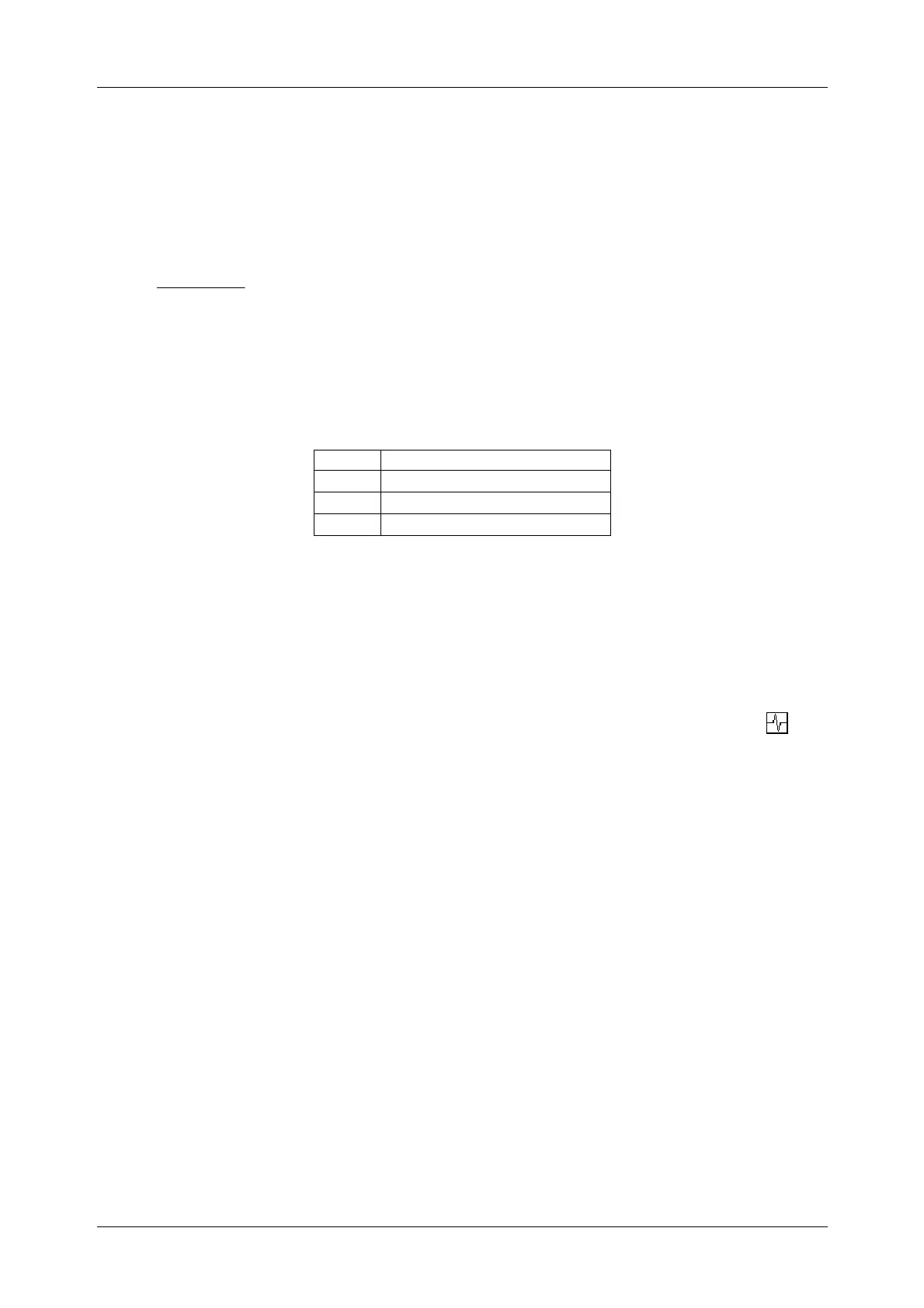
High fluctuations of the nominal voltage might influence the measuring results ( icon
on the LC display). In this case, it is recommended to repeat the measurements and to
check whether the measuring results are stable.