BestCode Next Series 8 Technical Manual October 2022 Page 191 of 290
Viscosity Check During Run
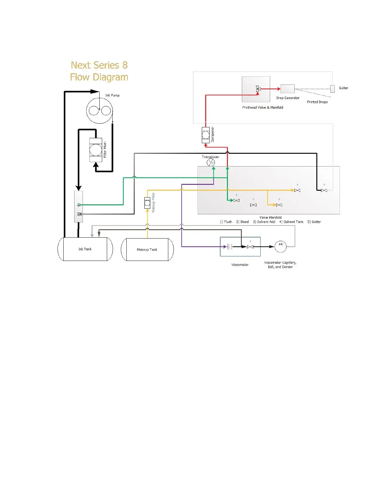
This diagram shows how the viscosity check occurs in the machine.
Viscosity Check Flow Logic: Active Valves: Printhead, Gutter, Viscometer.
1) The Standard “Run” Operation is occurring.
2) The Viscometer Valve Activates and pushed the Metal Ball to the top of the Viscometer.
3) After 30 Seconds, the Viscometer Valve De-Activates and the Ball begins to fall.
4) A timer is started to measure how long until the Ball passes the Inductive Sensor.
5) The Time is captured and converted to a value in cP.
6) The Target Viscosity is ALWAYS 4.5 cP.