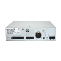
MCS-D 200 – Putting into operation
11
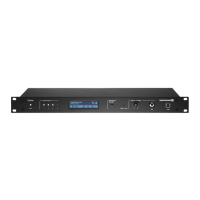
3.2.5 Rack mounting
• When mounting the MCS-D 200 control unit into a 19"-rack housing leave 1 U for a ventilation panel above and under the
control unit.
• Make sure that the mains switch, mains plug and all connection on the rear of the device are easily accessible.
3.2.6 How to supply the System
• All microphone stations, D/A interfaces and adapters are powered via the system. They do not have their own power supply.
• The number of the required power supply units depends on the number of microphone stations and the system set-up
including different cable lengths and operating mode.
• The following list shows how many devices such as microphone stations, interfaces and adapters can be powered by the system.
MCS-D 200 control unit with 1 power pack (= 2 A) for approx. 15 microphone stations
MCS-D 200 control unit with 2 power packs (= 4 A) for approx. 30 microphone stations
When the system is extended with additional power supply units:
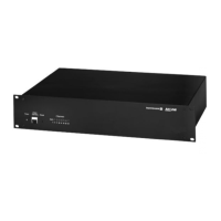
CA 4146 power supply unit (6 A) for approx. 45 microphone stations
Note:
In this rule of thumb, an adapter (CA 4212/13/14 or CA 4222/23/24) approximately counts as half a microphone station.
Example of a system set-up:
1 MCS-D 200 control unit with 2 power packs. . . . . . . . . . . . . . . 10 MCS-D 202 interpreter stations
+ 1 D/A interface
+ 2 adapters
+
1 CA 4146 power supply unit. . . . . . . . . . . . . . . . . . . . . . . . . . . . for 45 microphone stations
In case of doubt please contact beyerdynamic.
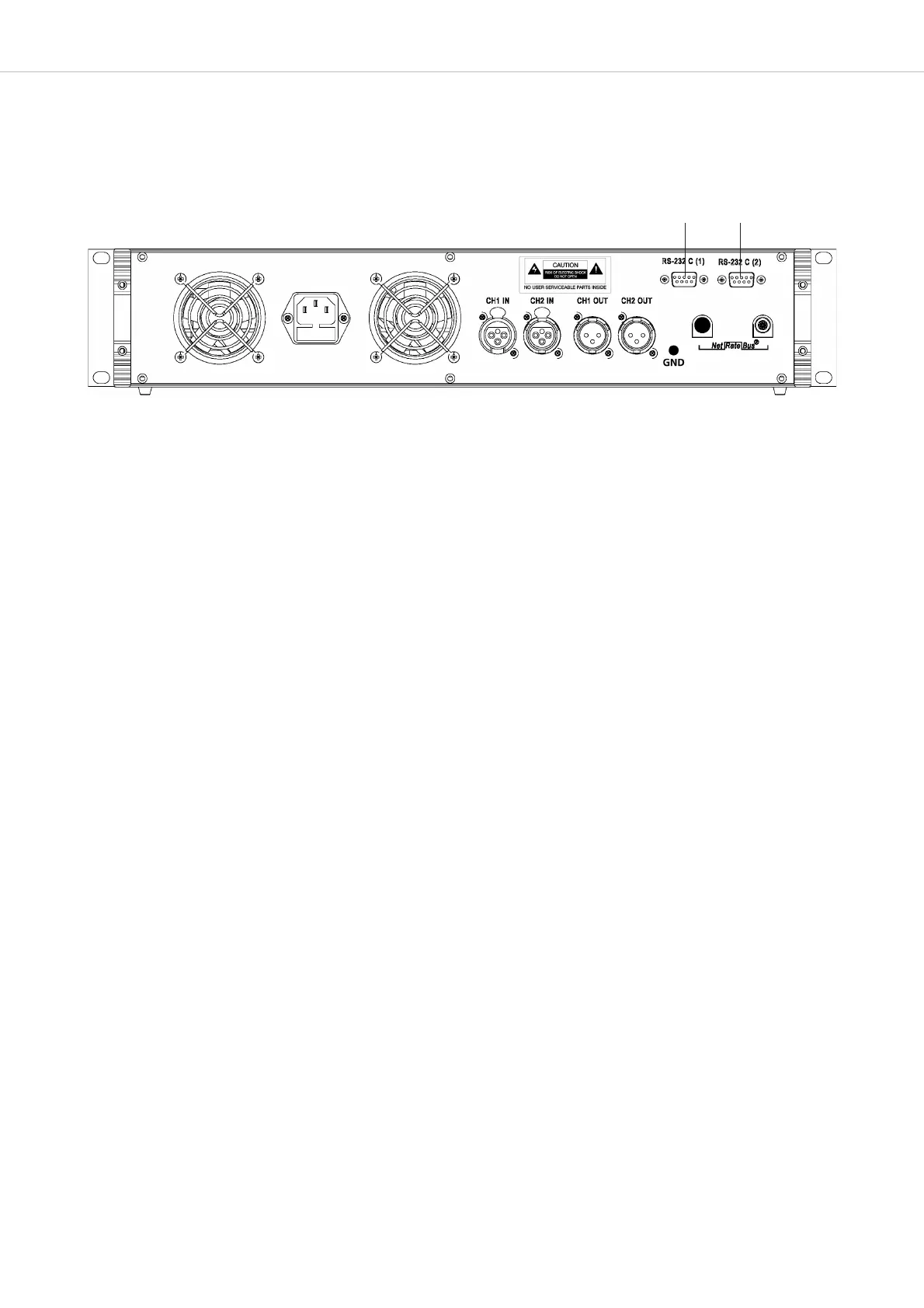
3.2.4 How to connect a PC or Media Control System
• If you would like to connect a PC or media control system to the MCS-D 200 control unit, use the RS 232 connection or .
• In order to connect a PC use a standard RS 232 null modem cable. If you connect other devices, please observe the pin assignment.
• The system is configured via the MCS-D 200 control unit, please refer also to chapter 3.3 “How to operate the menu of the MCS-D 200
control unit”.