13
BIFFI F01-2000 ELECTRIC ACTUATOR
INSTRUCTION AND OPERATING MANUAL
5�7�1 Remote commands
Using the “VIEW and SET-UP” features may
configure different control modes.
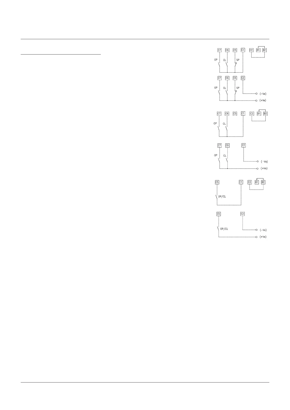
4 WIRES (see the remote connections diagram)
In “4 wires latched” (OPEN, CLOSE, STOP,
COMMON) mode, with the OPEN or CLOSE
signal switched to ON, the motor is energized,
and it runs on after the signal returns to OFF.
To stop the motor, press STOP. To reverse
the direction, press STOP and then press the
button relevant to the opposite direction.
OPTION A1)
OPTION B1)
3 WIRES (see the remote connections diagram)
With option “3 wires” (OPEN, CLOSE, COMMON),
the actuator can be driven in either “push-to-
run” or “latched with instant reverse” mode.
In “ push-to-run ” mode, the actuator can be
driven to the desired position by switching the
OPEN or CLOSE signal to ON. As the signal
returns to OFF, the motor is de-energized.
In “latched with instant reverse” mode, when
the OPEN or CLOSE signal switches to ON,
the motor is energized, and it runs on after the
signal returns to OFF. If the signal relevant to
the opposite direction goes ON, the actuator
reverses its direction and maintains the new
direction also if the signal returns to OFF.
The circuits associated to the inputs can be
supplied by the internally-generated 24 V DC
or by an external 20-125 V DC or 20-120 V AC
(50/60 Hz).
The signal levels are the following:
- Minimum ON signal > 20 V DC or 20 V AC
(50/60 Hz)
- Maximum ON signal < 125 V DC or 120 V AC
(50/60 Hz)
- Maximum OFF signal < 3 V DC or V AC
5�7�2 Output contacts
- Monitor relay: on the terminal board, the
voltage-free, change-over contacts of the
monitor relay are available. The monitor relay
indicates that the actuator can be remotely
controlled or that there is a problem or
condition which prevents remote control of
the valve. The conditions that cause the relay
to switch over are listed in paragraph 9.1.6,
Output relays.
- AS1,2,3,4 relays: on the terminal board, the
voltage-free contacts of 4 latching relays are
available. The status (make or break) and the
conditions that cause the switching of the
relay can be viewed and configured by using
the “VIEW and SET-UP” features. The status
of the latching relays is immediately updated
as the associated conditions for change
occur. Moreover, the status of the above
contacts is cyclically updated (every 500 ms)
- Contact rating:
Max. voltage 250 V AC/30 V DC
max. current 5 A;
Min. voltage 5 V DC;
min. current 5 mA
2 WIRES (see the remote connections diagram)
With the “2 wires” option 2 different activities
may be selected:
In “2 wires, signal ON to open”, the actuator
opens if the signal switches to ON and closes
if the signal goes to OFF. In “2 wires, signal
ON to close”, the actuator closes if the signal
switches to ON and opens if the signal switches
to OFF.
OPTION A2)
OPTION B2)
OPTION A3)
OPTION B3)
5�7 REMOTE CONTROL
Place the 3-position selector in REMOTE to
transfer the actuator control to a remote
device. LocalOPEN or CLOSE operation will
be inhibited. Only local STOP control remains
active.
Using the “VIEW and SET-UP” features may
configure different control modes. The remote
controls are opto-coupled.
A non-regulated 24 V DC voltage (variable from
23 to 27 V DC, max. 4 W) is available on the
actuator terminal board to supply the remote
controls or external devices.
- Minimum signal duration > 300 ms.
- Total current drawn from remote controls
< 25 mA
5�7�3 ESD operation
An ESD (Emergency Shut Down) signal
can be sent to the actuator to override any
existing command and to drive the valve to a
predetermined position.
The control is not self-maintained, that is, the
ESD action continues until the relevant signal is
present. The “VIEW and SET-UP” features can
configure different ESD options.
The ESD command is opto-coupled.
Thecircuits associated to the input can be
supplied by the internally generated 24 V DC
or by an external 20-125 V DC or 20-120 V AC
(50/60 Hz).
The signal levels are the following:
- Minimum ON signal > 20 V DC or 20 V AC
(50/60 Hz)
- Maximum ON signal < 125 V DC or 120 V AC
(50/60 Hz)
- Maximum OFF signal < 3 V DC or V AC
- Current drawn from ESD controls < 15 mA
WARNING
If customers wish the motor thermostat to be
by-passed during ESD operation any certification
for actuator enclosure in hazardous area would be
invalidated.

 Loading...


