14
BIFFI F01-2000 ELECTRIC ACTUATOR
INSTRUCTION AND OPERATING MANUAL
5�8 OPERATING THE F01-2000 FOR THE
FIRSTTIME
Before attempting to operate the F01-2000
for the first time, check that the actuator is
correctly mounted on the valve. Place the
3-position selector in OFF and switch the
power on. The alphanumeric display shows the
following message for about 3 seconds:
5�9 OPTIONAL MODULES
Additional modules can be plugged in the base
card of the F01-2000 to provide the following
functions:
5�9�1 Fieldbus interface for remote control via
FIELDBUS
This card allows to connect the F01-2000 to
FIELDBUS.
The following bus interface cards are available:
- Profibus DPVO
- Profibus DPV1 with or without redundancy
- Foundation Fieldbus
- LonWorks
- Modbus RTU
A Hardware alarm is generated if the F01-2000
was set to be equipped with bus card, but the
card is damaged or missing. A BUS REPORT
is also present in the list of reports if the card
is present (see chapter 6). See the specific
manuals for instructions and the setting of the
above modules.
Then the new message should be:
according to the configuration present in the
memory.
If the upper line of the display shows
“ALARM OFF”, remove the alarm before
going ahead (see paragraph 12.10).
If the upper line of the display shows
“WARNING OFF”, a warning condition
is present. You can go ahead since the
F01-2000 is working well, but some datum is
not according to the configured parameters
(seeparagraph 12.10).
If the following message appears, the base
card is F01-2000 v4 type, but the actuator is
equipped with an F01-2000 v0 series terminal
board. This may happen if the F01-2000 v4 base
card was supplied as a spare card, to replace
the base card of the F01-2000 v0 series (see
the previous revision of instruction manuals
relevant to the F01-2000 and its optional
modules).
5�9�2 Ain/Aout card
With the above card the F01-2000 is provided
with a 4-20 mA analog input and a 4-20 mA
analog output. This card should be plugged
on the base card, replacing the “TERMINAL
BOARD ADAPTOR” card supplied as standard.
A Hardware alarm is generated if the F01-2000
or
Biffi Italia
F01-2000 v4 ntb
NORMAL OFF
STOP
NORMAL OFF
R%: xxx�x
Biffi Italia
F01-2000 v4 otb
Do not operate the actuator without first
checking that the configuration is according to
the required application by using the “VIEW and
SET-UP” features (see chapter 6/10).
Set torque limits, position limits and close
direction by means of the “stroke limits
routine” of the “actuator set-up” menu
(see chapter 9).
When the stroke limits and the configurations
are correct, bring the 3-position selector to
LOCAL and drive the actuator to open or closed
position (see paragraph 5.4).
If the upper line of the display shows
“INT OFF”, an Interlock input is active.
If the upper line of the display shows
“ESD ON OFF”, the ESD input is active.
was set to be equipped with an Ain/Aout
card, and the card is damaged or missing.
An Ain/Aout REPORT is also present in the list
of reports if the card is present (see chapter 6).
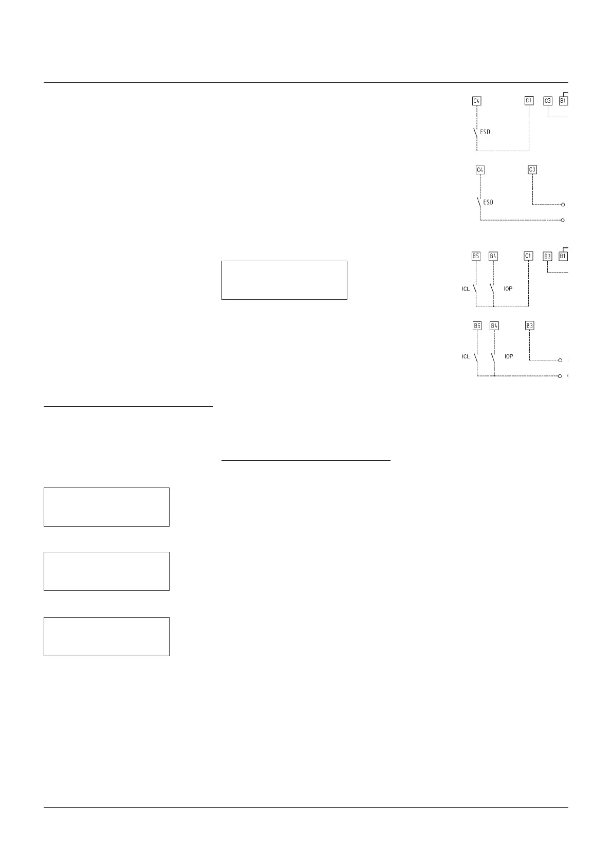
5�7�4 Interlock inputs
Two additional inputs are available to inhibit
actuator movement in open or close direction.
The controls are momentary, and the inhibit
action continues until the relevant signal
is present. The interlock controls work
when the local selector is in either LOCAL
or REMOTE positions. The ESD control
overrides the interlock controls. The “VIEW
and SET-UP” features can configure the
polarity of INTERLOCK signal as described in
paragraph9.1.10, Interlock.
The interlock inputs are opto-coupled and can
be supplied by the internally generated 24 V DC
or by an external 20-125 V DC or 20-120 V AC
(50/60 Hz).
The signal levels are the following:
- Minimum ON signal > 20 V DC or 20 V AC
(50/60 Hz).
- Maximum ON signal < 125 V DC or 120 V AC
(50/60 Hz).
- Maximum OFF signal < 3 V.
- Total current drawn from remote controls
< 20 mA.
OPTION D1)
OPTION D2)
OPTION E1)
OPTION E2)

 Loading...


