47
1
2
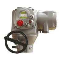
BIFFI F01-2000 ELECTRIC ACTUATOR
INSTRUCTION AND OPERATING MANUAL
WARNING
The actuator is non-intrusive. The control
compartment was sealed in dry and clean conditions
and contains no site serviceable components.
Do not open it unless absolutely necessary.
Unauthorized acces will invalidate the warranty.
WARNING
Since the control compartment contains a3.6V
lithium battery type LS 14500C (SAFT), only
open it in safe area. Ifthe actuator is located in
a hazardous area, a“hotwork” permit must be
obtained unless the actuator can be moved to a
non-hazardous area.
12 TROUBLESHOOTING
The F01-2000 actuator has passed the
functional test performed by Biffi Quality
Assurance personnel.
12�1 THE ELECTRONICS DO NOT SWITCH ON
WHEN POWERED
• Check that the value of the main voltage on
terminals L1, L2, L3 is correct.
• Remove the cover of the compartment where
the electronic cards are located.
• Check the fuse mounted on the power card.
Replace it if burnt.
• If the fuse is OK, check the wires between
terminals L1, L2, L3 and connector M1 of
the power card. If it is correct, replace the
powercard.
12�2 DC OUTPUT VOLTAGE NOT AVAILABLE
AT THE TERMINALS
• Switch the main power supply off and
disconnect all wires from terminals B1-B2
and C1.
• Switch the main power supply on and check if
the voltage on the terminals B1-B2 and C1 is
between 23 and 27VDC.
• If the voltage is correct check the external
wiring and the electrical load. It should not
exceed 4 W.
- If the voltage is not correct replace the
power card.
1. Power card
2. Fuse
12�3 THE ACTUATOR DOES NOT WORK FROM
REMOTE CONTROLS
• Move the 3-position selector to LOCAL and
check that the actuator works from local
controls.
• Move the local selector to REMOTE. If the
ESD signal is active, the alphanumeric
display indicates “ESD On”. Check the signal
on terminals C3 and C4 and adjust the ESD
configuration.
• Check that:
- the wiring to terminals B1-B2 and C1 is
correct
- there is no short-circuit between wires
- the electrical load does not exceed 4 W
- the value is in the range 20-120 V AC
50/60Hz or 20-125 V DC, if external voltage
supply is used.
If the actuator does not work,
before troubleshooting make sure that:
- The numeric display indicates xx %
- The local selector is not in OFF
- The main supply voltage is the same as stated
in the nameplate menu
- You move the local selector to OFF and check
that the alphanumeric display shows one of
the following messages:
- “normal, off, stop”
- “alarm, off, stop”
- “warning, off, stop”
If the above checks are satisfactory try to locate
the fault using the diagnostic facilities.

 Loading...