9
BIFFI F01-2000 ELECTRIC ACTUATOR
INSTRUCTION AND OPERATING MANUAL
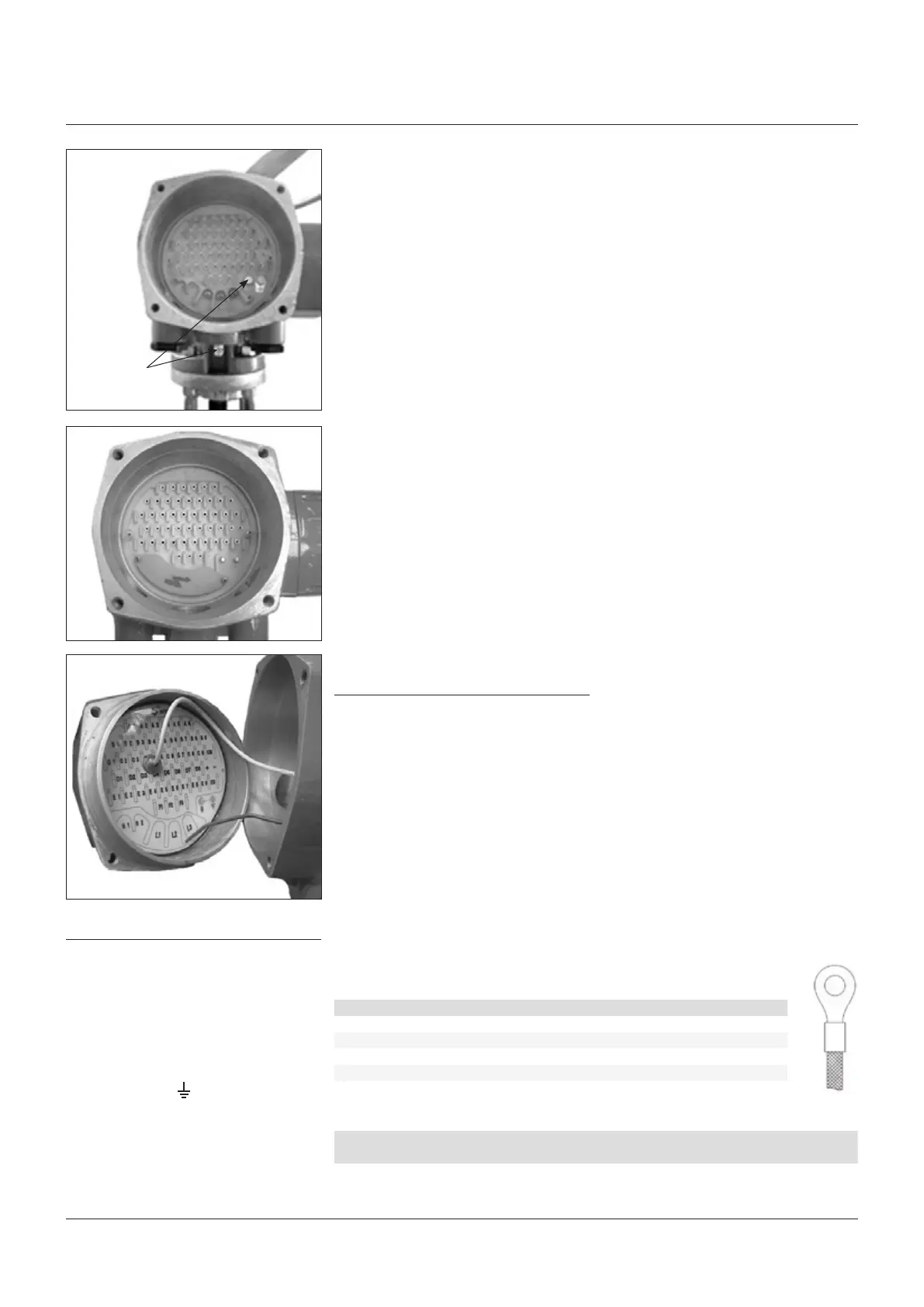
Terminate the ground connections to the
ground stud marked One internal
andoneexternal ground studs are provided.
Check the wiring diagram (always enclosed
with the actuator) and the layout displayed
on the back of the terminals enclosure cover,
to ensure a correct electrical connection.
3�9 INSTRUCTIONS FOR THE
EXPLOSIONPROOF ENCLOSURES
IMPORTANT
Electric actuator F01-2000 shall be installed
and maintained according to the applicable
rules regarding the electrical installations in
hazardous area (other than mines) classified
as zone 1 (gas); example: EN 60079-10
(hazardousareaclassification), EN 60079-14
(electrical installation), EN 60079-17
(maintenance), and/or other national standards.
During the dismantling and subsequent
reassembling of the explosionproof enclosures
(covers, cable glands, joints) be careful to bring
these enclosures back to their original condition
3�8 TERMINAL BOARD
Ground studs
IMPORTANT
The removal of any other covers without Biffi’s
approval will invalidate the warranty. Biffi will
not accept any responsibility for any damage or
deterioration that may occur as a result of cover
removal.
Allterminations should be made by insulated
ring or spade connectors using the appropriate
crimping tool. This operation will ensure easy
and correct electrical connection.
Connect the motor supply cable previously
sized in accordance with:
- The absorbed current correspondent to the
actuator nominal torque with the torque
limiting device set at 100 percent (see the test
certificate attached to the actuator).
- The applicable plant and safety norms.
Assemble the power terminals protective
barrier, located in the terminal board
compartment, using the enclosed screws.
The control circuit (controls and signals) must
be connected by means of a multicore cable
to the corresponding numbered terminals
according to the wiring diagram.
The internal cables of the actuator are also
numbered according to the wiring diagram.
Actuators are always delivered with the
motors wound and connected in accordance
to customer requests. Voltage and frequency
values are stated on the motor nameplate.
Connections for Ex e terminals enclosure
The wires must be terminated in accordance
with the following method (see connection table
below):
CONNECTION TABLE
Power cables Control cables
Type of terminal Insulated ring tongue
Eye dimensions (mm) 5.50 3.20
Recommended tightening torques (Nm) 2.0 - 2.8 1.0 - 1.5
Wires section (mm
2
) 4 2.5
BOLTING TABLE
Model
Motor
cover
Terminal enclosure/
local interface covers Material
F01 M10x35 M10x30 AISI 316/ASME B16.11 A182-F316 (yield strength ≥ 450N/mm
2
)
to maintain their integrity. In particular, be
sure the joint surfaces of all enclosures are
spread with a film of recommended grease
(seechapter4, Lubrication).
So please:
• Do not damage the explosionproof mating
surfaces on the housing and on the electrical
enclosures covers.
• Reinstall all the screws that go with the
dismantled parts, and block them with a
thread sealant after spreading them with
a film of copper- or molybdenum-based
grease. This will keep screws from sticking
and make maintenance operations easier.
• Check that the bolts and screws are the
same dimension and quality as the original
ones (see bolting table below), or of a
betterquality.
 Loading...


