17
4
6
1
3
2
5
BIFFI F01-2000 ELECTRIC ACTUATOR
INSTRUCTION AND OPERATING MANUAL
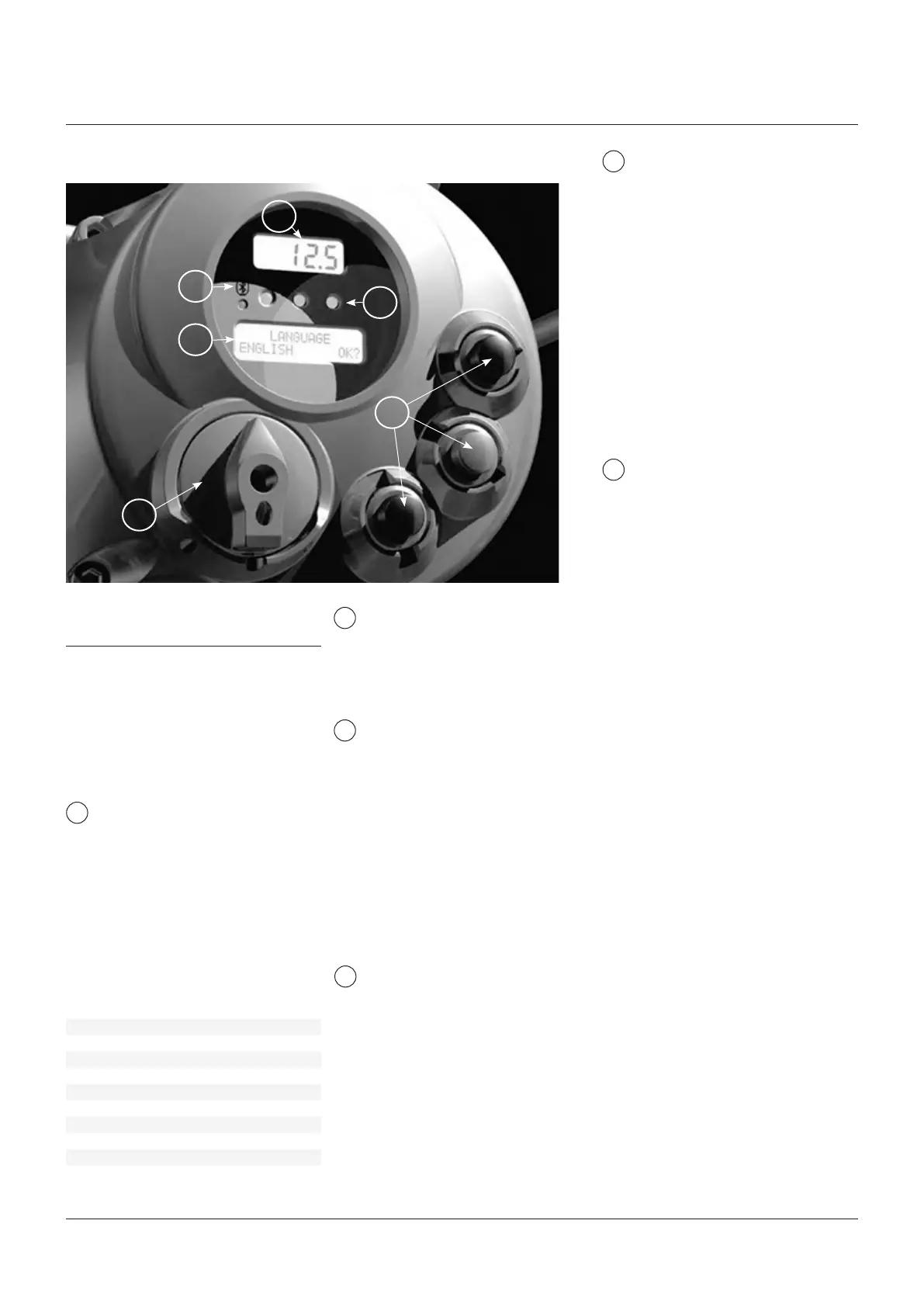
6 LOCAL CONTROLS
Numeric display to indicate the present
valve position as a % of the opening.
Display resolution in function of the actuator
stroke turns:
- From 2.8 to 5.5 turns = 1%
- From 5.5 to 13.8 turns = 0.5%
- From 13.8 to 27.7 turns = 0.2%
- From 27.7 to 10,000 turns = 0.1%
3-position selector to set the following
operation modes:
- LOCAL: for local control only
- OFF: no control is active but the actuator is
still connected to the mains
- REMOTE: for remote control only
Alphanumeric display: during normal
operation the alphanumeric display shows the
present status (NORMAL, ESD ON, ALARM,
WARNING, INTERLOCK), the 3-position
selector status (LOCAL, OFF, REMOTE) and the
actuator action (OPEN, OPENING, CLOSED,
CLOSING, STOP or
R% : xxx.x). If the local selector is in OFF or
REMOTE, pressing the YES push-button it is
possible to scroll the list of variables, alarms
and reports:
CLOSE/NO
STOP
OPEN/YES
The F01-2000 can be provided with a
radiofrequency wireless connection based on
a qualified Bluetooth™ class 1 module. This
allows to establish a connection and exchange
data with a PDA or PC with built-in Bluetooth™
technology. The following tasks can be
wirelessly performed:
- View and change configuration
- Set maintenance function
- Read maintenance data
- Download new firmware to the F01-2000
- The blue LED indicates that the
communication with a host device is
established
Local controls: OPEN/YES, CLOSE/NO,
and STOP push-buttons.
The STOP push-button resets any existing
command and is active both in local and
remote.
If the 3-position selector is in LOCAL, the
OPEN / YES, and CLOSE /NO push-buttons
work as OPEN and CLOSE commands.
If the 3-position selector is in REMOTE or
in OFF, the OPEN / YES and CLOSE / NO
push-buttons work as YES and NO to answer
the prompt (next? OK? view?, change? exit?) of
the alphanumeric display.
In OFF, the OPEN / YES and CLOSE / NO
push-buttons allow to scroll down the menu,
to view and change the actuator configuration
or to scroll the list of variables, status, and
alarms.
In REMOTE, the above push-buttons allow
scrolling the list of variables, status, alarms
and reports but the actuator configuration
cannot be viewed or changed.
6�1 DESCRIPTION OF THE LOCAL OPERATOR
INTERFACE
The following functions are available by the
F01-2000 local operator interface:
- actuator control
- actuator configuration
- actuator status visualisation
The figures on the following pages describe
the function of each component of the local
operator interface.
1
3
2
4
5
6
output torque mot temp
motor speed term temp
main voltage log status
current wireless report
temperature node report *
time FDI report *
date base report
alarm term report
warning Ain/Aout report *
Ktemp
The data with * are only present if the relevant
modules are present.
Three LED’s to indicate the actuator
status according to the following logic:
- green ON/ red OFF: the actuator is stopped in
open position
- green OFF/ red ON: the actuator is stopped in
closed position
- green OFF/ red flashing: the actuator is
running in closing direction
- green flashing/ red OFF: the actuator is
running in opening direction
- green ON/ red ON: the actuator is stopped in
intermediate position
- yellow ON: alarm
- yellow flashing: warning
The above color combination is supplied as
standard, but it may be changed (red with
green, green with red, and yellow with red),
during actuator setting operations.

 Loading...


