12
BIFFI F01-2000 ELECTRIC ACTUATOR
INSTRUCTION AND OPERATING MANUAL
5�3 ELECTRICAL OPERATION
Before connecting power to the actuator check
that the voltage is correct and according to the
indications on the nameplate. Wrong power
supply could cause a permanent damage to the
electrical components. Check of phase rotation
is not necessary since the unit is provided with
automatic phase rotation correction. Place
the 3-position selector in OFF and then switch
on the power. Do not operate the actuator
without first checking that the configuration is
according to the required application. Usingthe
“VIEW and SET-UP” features can do this
(seeparagraph 6.4, Local controls - Entering
the set-up mode).
5�4 LOCAL CONTROL
After configuring the actuator, if no alarm is
present, place the 3-position selector in LOCAL
and control the actuator by OPEN, CLOSE and
STOP push-buttons.
If “push-to-run” was selected the actuator can
be driven to the desired position by pressing
and holding the OPEN/YES or CLOSE push-
button. As the push-button is released, the
motor is de-energized.
If “latched” was selected, as the OPEN or
CLOSE push-button is pressed the motor is
energized, and it runs on after the control
is released. To stop the motor, press the
STOP push-button. Toreverse the direction,
press the STOP push-button and then press the
push-button relevant to the opposite direction.
In “latched with instant reverse” mode, the
local controls work as in the “latched” mode,
but to reverse the motor direction you only
need to press the push-button relevant to the
opposite direction.
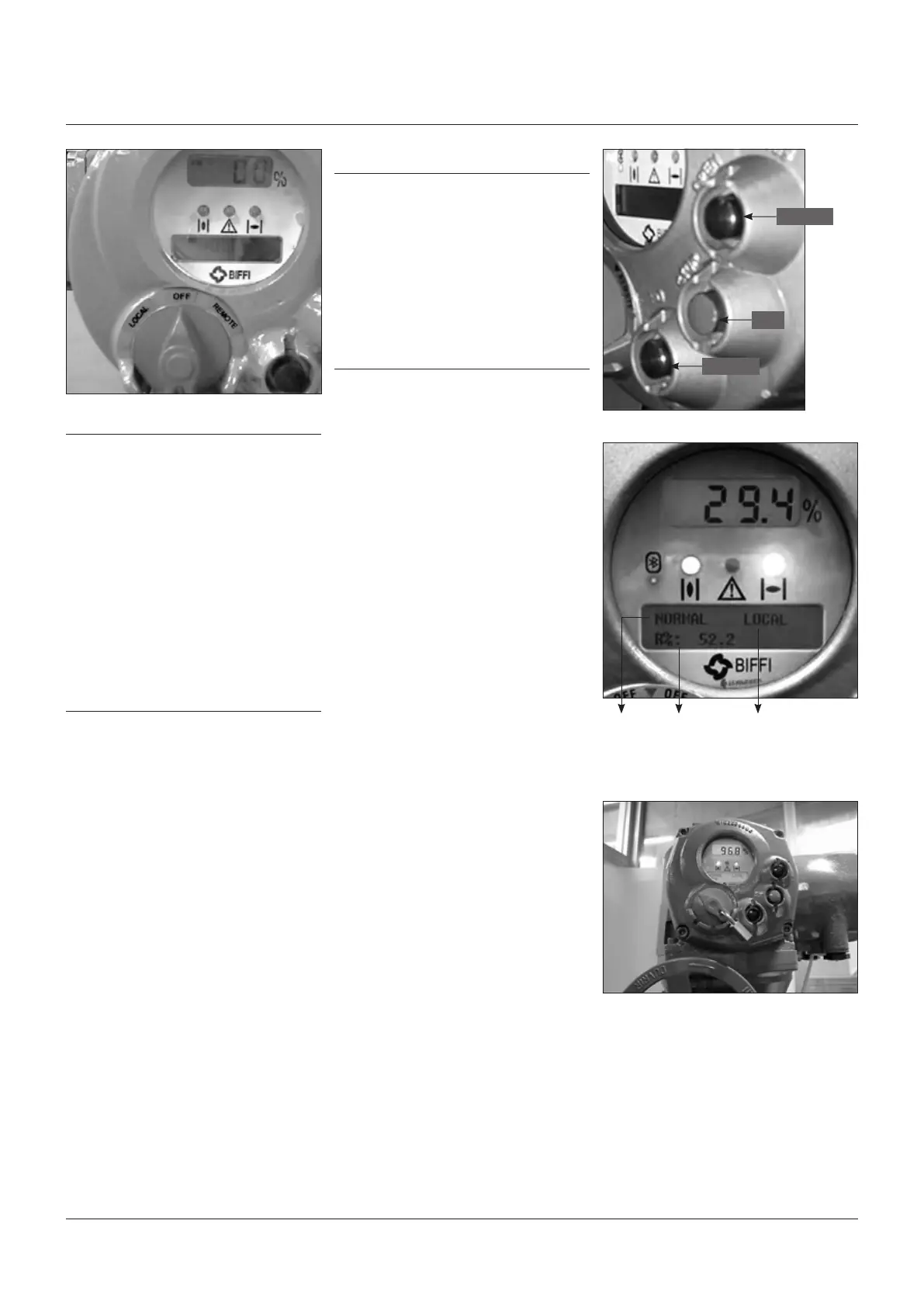
5�5 LOCAL INDICATION
The upper display (3½ LCD) indicates the
valve position as a percentage of opening
(open=100%).
The lower display has two alphanumeric lines.
The upper line indicates the actuator status and
the 3-position selector status. The lower line
indicates the actuator operation.
Two LED’s indicate the actuator position /
operation, while a third LED indicates alarms.
5�6 LOCK OF THE 3-POSITION SELECTOR
The 3-position selector can be locked in any of
its three positions by means of a padlock.
OPEN/YES
STOP
CLOSE/NO
Status Operation
or Position
request R%
Local selector
position

 Loading...


