15
B6
B7
B7
C10
B9
B8
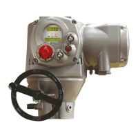
BIFFI F01-2000 ELECTRIC ACTUATOR
INSTRUCTION AND OPERATING MANUAL
• 4-20 mA analog output
The 4-20 mA output can be configured to
provide a signal proportional to either “position”
or “torque”. The polarity option allows to
reverse the relationship between the position
or torque and the 4-20 mA output signal. See
“VIEW and SET-UP” features (paragraph 9.1.9,
OUT 4-20 mA).
The 4-20 mA output is opto-coupled. It should
be powered by a 20-30 V DC voltage (externally
or internally generated) and the maximum load,
including the cable resistance, should be less
than 300 ohm.
Figure A shows the wiring diagram.
Actuator terminals
ACTIVE LOOP
Cable
GROUND
Shield
20-30
V DC
External power supply
LOAD: max 300 ohm
Internal power supply
Cable
GROUND
Shield
LOAD: max 300 ohm
The behaviour in case of loss of main
voltage is different if the power supply of the
4-20 mA output stage is internally or externally
generated:
- Internal power supply (or passive loop):
In case of loss of main voltage the output
4-20 mA drops to 0. The correct output will be
restored when the main voltage returns.
- External power supply (or active loop):
If the actuator is provided with an lithium
battery (or supplied by the auxiliary 24 V DC)
and if the main voltage fails, the output
4-20 mA maintains the last value. If the
actuator is moved by handwheel, the output
4-20 mA will be updated.
If the actuator is not provided with an lithium
battery (or not supplied by the auxiliary
24 V DC) and if the main voltage fails, the
output 4-20 mA maintains the last value.
If the actuator is moved by handwheel, the
output 4-20 mA will not be updated.
• 4-20 mA analog input
The 4-20 mA analog input is the position
request R% signal and is used by the F01-2000
to position the valve in inching and modulating
actuators. The “POSITIONER” routine
processes the input signal, compares the
present actuator position % with the position
request R% and if the difference is greater than
the dead band, the actuator is driven to reach
the requested position. 4 mA corresponds to
request R% = 0% = valve closed and 20 mA
corresponds to request R%=100% = valve
open. The relationship between position
and request signals can be reversed by the
“Polarity” function. The 4-20 mA input is
opto-coupled. The input impedance is less than
500 ohm. The loss of the 4-20 mA input signal
is indicated as follows:
- Change-over of the monitor relay
- Alarm LED on
- List of ALARMS (see paragraph 12.10,
Diagnostic messages)
- Alarm log
Figure B shows the wiring diagram.
Actuator terminals
Cable
0 V DC
4-20 mA
GROUND
Shield
4-20 mA
generator
PASSIVE LOOP
4-20 mA
0 V
4-20 mA
FIGURE A
FIGURE B
The “VIEW and SET-UP” features can configure
different options which are described in
paragraph 9.1.7, Positioner.
If the POSITIONER function is active the
alpha-numeric display indicates the value of the
position request in % (R%: xxx.x).
NORMAL REMOTE
R:47% NEXT?
0 V
V+
0 V

 Loading...