22
© Copyright by BIFFI Italia. All rights reserved.
A !@#$ INTERNATIONAL LTD. COMPANY
F02 Quarter-turn Electric Actuators
instruction and operating manual
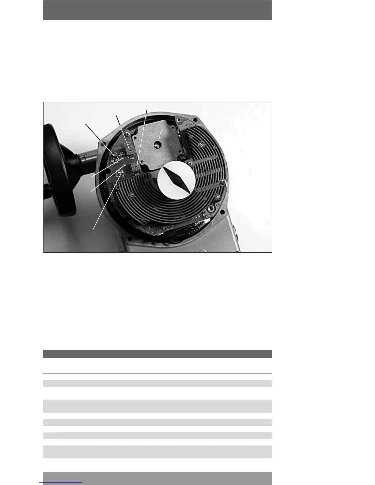
F02 internal control panel and setting tools.
Rotary selector switch SW6
Rotary selector switch SW4
Pushbutton SW5
Green LED:
Power on
Red LED:
Enter
confirmation
Selector switch SW3
The setting of the actuator parameters is done through the following tools:
- two rotary selector switches SW6 and SW4 for actuator setting;
- Enter push-button SW5 (confirmation push-button);
- dip-switch SW3 (enable setting function);
- green LED indicating power On (switched on when power supply is available).
- red LED for Enter confirmation (blinking once setting is confirmed);
- mechanical stops.
6.2.2 ACTUATOR MODEL SELECTION
The frames relevant to models 63/125 and 250/500 can be set to operate with a 63Nm or
125Nm motor and a 250Nm or 500Nm motor respectively.
The difference is based on the technical characteristics of the electric motor itself.
The selection of the actuator model must be done through selector switches SW4 and SW6
as indicated in the following setting table.
F02 configuration and setting table
Switch SW4 SW6 SW5 SW3
Enter Setting Default
pushbutton function values
Close limit 0 0 1 1
Open limit 1 0 1 1
Limit switch closing 2 1: position 1 1 position
0: torque
Limit switch opening 3 1: position 1 1 position
0: torque
Closing stroking time 4 0 to 9 1 1 7
Opening stroking time 5 0 to 9 1 1 7
Torque CL 6 0 to 9 1 1 9
Torque OP 7 0 to 9 1 1 9
Reverse mode (CCW) 8 0 = off; 1 = on 1 1 OFF
Size 9 0: 63Nm (250 Nm) 1 1 63 Nm or
1: 125Nm (500/1000 Nm) 250Nm