December 2019
142
Installation, Operation and Maintenance Manual
VCIOM-08500-EN
Appendix
Appendix
C.7.3 Electrical Connections
The electrical connections shall be made in accordance with the wiring diagram and
to the general instructions associated with the documentation of the base unit.
C.7.3.1 Connection for Ex-e Terminals Enclosure
The wires must be terminated in accordance with the following method:
Type of terminal: Insulated ring tongue
Eye dimensions: 5.5 mm (0.22 in) for power cable
3.2 mm (0.13 in) for control cables
Recommended tightening torques: 2.0 - 2.8 Nm (17.7 - 24.8 lb.in) for power cables
1.0 - 1.5 Nm (8.9 - 13.3 lb.in) for control cables
Wires section: 4 mm² (0.006 in²) for power cables 2.5 mm²
(0.004 in²) for control cables
C.7.4 Cable Connection
Sealing of conduit entries must be carried out in accordance with national standards or as
indicated by the relevant regulatory authorities.
Sealing methods and cable glands must be approved and separately certied for use in
hazardous areas.
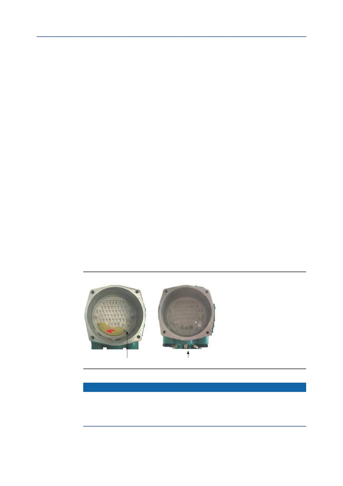
Two earth connection points - one internal and one external - are located on the
ICON3000 base model (see Figure C-3) for connection to ground cables.
Figure C-3
NOTICE
To prevent water inltration through the line cable conduits, be sure the cable glands used
possess the minimum degree of protection required by the plant and are specied on the
actuator label. If a rigid conduit makes a connection to the plant, it is recommended to place a
exible pipe connection between the conduit and the conduit entry of the additional extension.
Internal earth stud External earth stud