December 2019
33
Installation, Operation and Maintenance Manual
VCIOM-08500-EN
Operating the ICON3000
Section 5: Operating the ICON3000
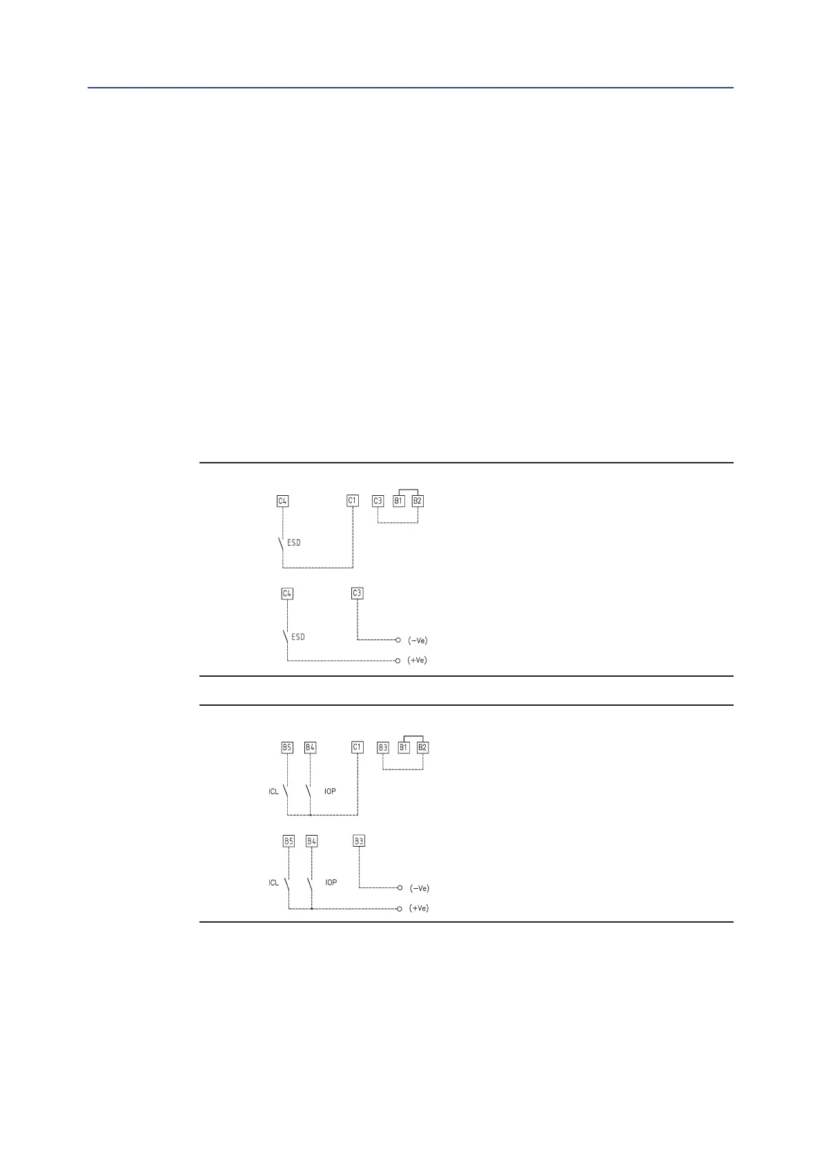
5.6.4 Interlock Inputs
Two additional inputs are available to inhibit actuator movement in the open or closed
direction. The controls are momentary, and the inhibiting action continues until the
relevant signal is present. The interlock controls work when the local selector is in either
LOCAL or REMOTE positions. The ESD control overrides the interlock controls. The “VIEW
and SET-UP” features can congure the polarity of INTERLOCK signal as described in
Section 9.1.10, Interlock Controls.
The interlock inputs are optically-isolated (opto-coupled) and can be supplied by the
internally generated 24 V DC or by an external 20-125 V DC or 20-120 V AC (50/60 Hz).
The signal levels are the following:
• Minimum ON signal > 20 V DC or 20 V AC (50/60 Hz).
• Maximum ON signal < 125 V DC or 120 V AC (50/60 Hz).
• Maximum OFF signal < 3 V.
• Total current drawn from remote controls < 20 mA.
Figure 39
Figure 40
Option D1)
Option D2)
Option E1)
Option E2)