December 2019
153
Installation, Operation and Maintenance Manual
VCIOM-08500-EN
Appendix
Appendix
D.7.4 Cable Connection
When optional extensions for additional entries or additional electronic cards are
connected to external cables or conduits, the sealing of these entries must be carried
out in accordance with the national standards or regulatory authorities that certied
the extension(s). The method of sealing and cable glands used must be approved and
separately certied for use in hazardous areas.
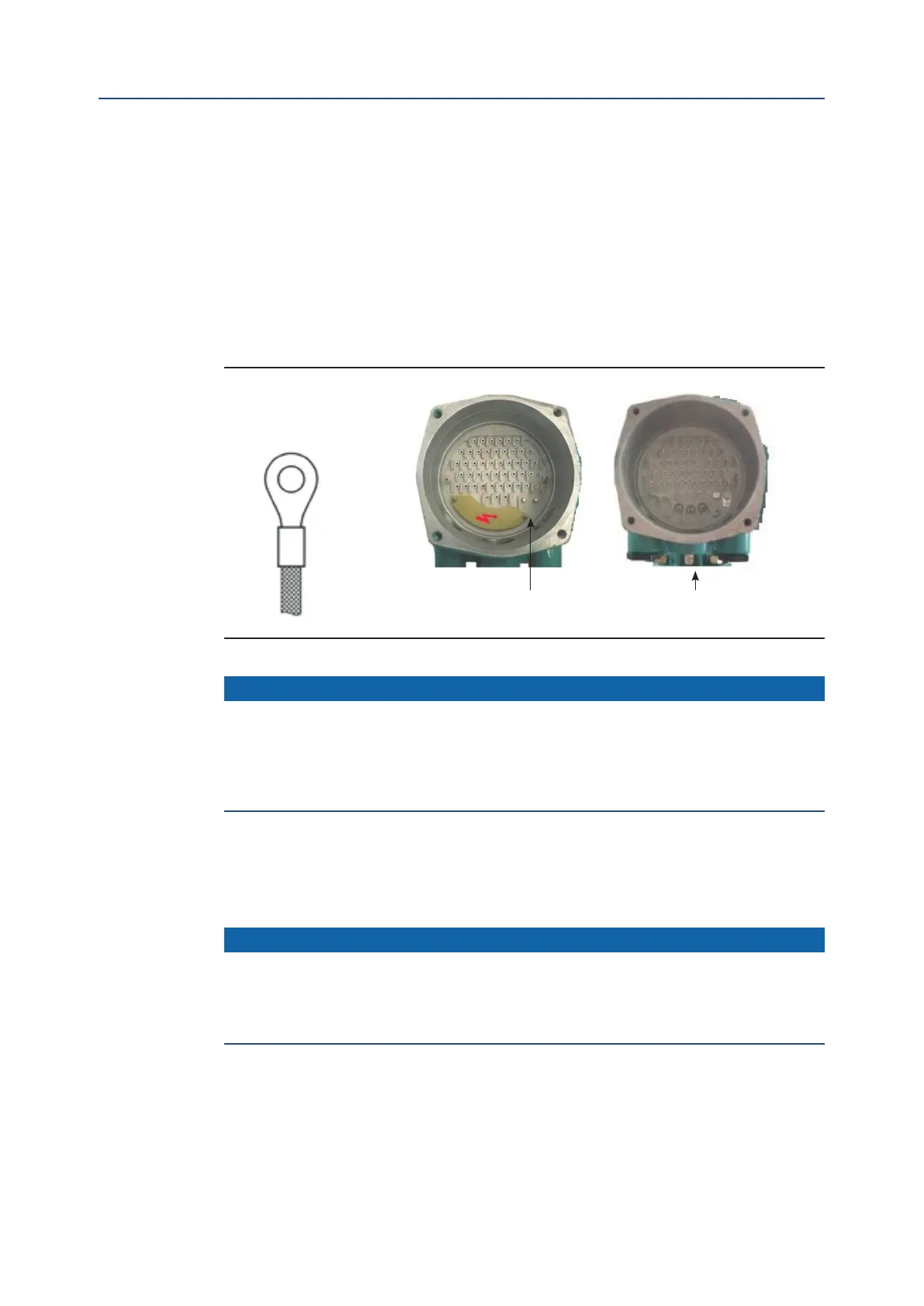
Two earth connection points - one internal and one external - are located on the
ICON3000 base model (see Figure D-6) for connection to ground cables.
Figure D-6
NOTICE
To prevent water inltration through the line cable conduits, ensure that the cable glands
used possess the minimum degree of protection required by the plant and are specied on
the actuator label. If a rigid conduit makes a connection to the plant, it is recommended to
place a exible pipe connection between the conduit and the conduit entry of the additional
extension.
To guarantee that the weather-proof and explosion-proof characteristics are maintained,
screw the cable gland or the external ATEX-certied apparatus tightly (at least 5 turns of
engagement) and coat them with a thread sealant.
NOTICE
All accessories (including cable glands) must comply with approved specications for the
site requirements and be certied according to the standard directive. When selecting
cables and cable glands, the maximum temperature of the cable (indicated on the product
label of the base ICON3000) must be considered.
Internal earth stud External earth stud
Connection for Ex-e
terminals enclosure