KBF / KBF-UL + KMF (E6) 09/2021 page 120/160
19.5 Zero-voltage relay alarm outputs for temperature and humidity (option)
The chamber equipment with optional zero-voltage relay outputs for temperature and
humidity (option) permits the transmission of alarms to a central
Connection is established via a DIN socket (6) located on the right lateral control panel.
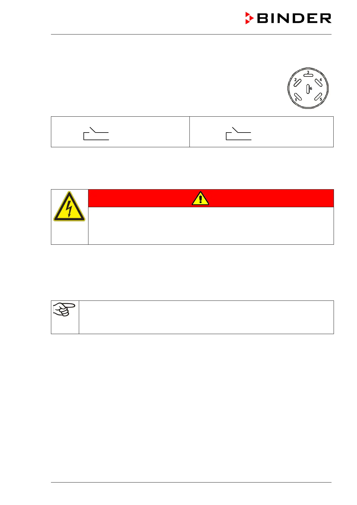
Figure 21: Pin configuration of the DIN socket (6)
Pin 1: Pin
Pin 2: Make
Pin 3: Pin
Pin 4: Make
In case of a temperature alarm, pins 1 and 2 are open; with humidity alarm, pins 3 and 4 are open. This
happens simultaneously with the alarm message shown on the controller display.
In case of power failure, both contacts are open.
Maximum loading capacity of the switching contacts: 24V AC/DC - 2,5A
DANGER
Electrical hazard through overload of contacts.
Deadly electric shock. Damage to the switching contacts and connection socket.
∅ Do NOT exceed the maximum switching load of 24V AC/DC – 2.5A.
∅ Do NOT connect any devices with a higher loading capacity.
A temperature and humidity alarm message will remain visible on the controller display during the whole
time of the alarm transmission via the zero-voltage relay outputs.
As soon as the cause of the alarm is rectified, you can reset the alarm transmission via the zero-voltage
relay outputs together with the alarm message on the controller.
In case of power failure, transmission of the alarm via zero-voltage relay outputs remains active for the
duration of the power failure. Afterwards, both contacts will close automatically.
When using the APT-COM™ 4 Multi Management Software (option, chap. 19.1) via the inter-
face of the constant climate chamber for data acquisition, the alarm is not automatically trans-
mitted to the APT-COM™ protocol.
Set the tolerance limits for recording limit value excesses separately in APT-COM™ 4.