KBF / KBF-UL + KMF (E6) 09/2021 page 29/160
4. Installation and connections
4.1 Spacer for wall distance
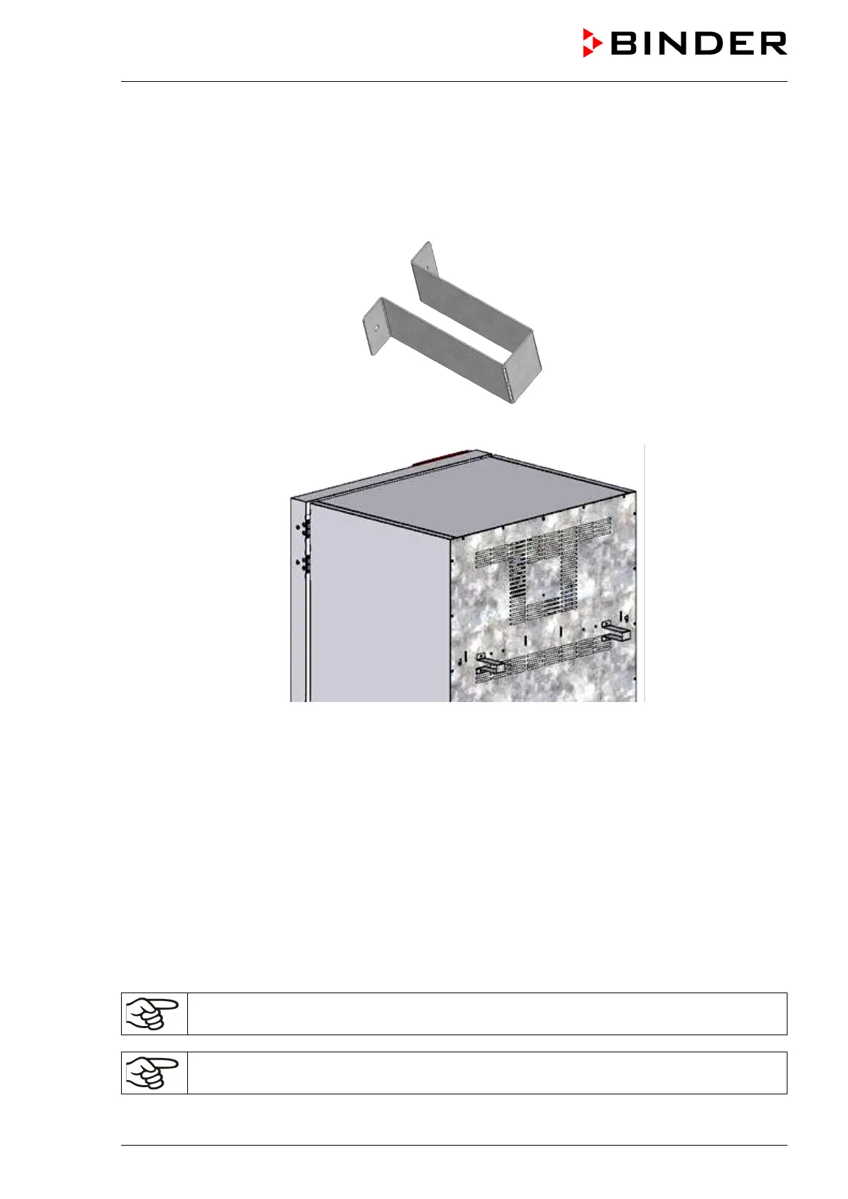
Please fix both spacers with the supplied screws at the chamber rear. This serves to ensure the prescribed
minimum distance to the rear wall of 100 mm / 3.94 in.
Figure 8: Spacer for wall distance
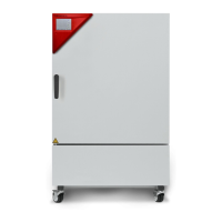
Figure 9: Chamber rear with mounted spacers
4.2 Wastewater connection
Fasten the wastewater hose to the wastewater connection “OUT” (14) on the rear of the chamber (olive ∅
14 mm). Observe the following points:
• You can use a part of the supplied water hose as a drainage hose. In case another hose is used, it has
to be permanently resistant against at least 95 °C / 203 °F.
• Mount the wastewater hose with a maximum positive inclination of 1 m and a maximum total length of
3 m.
• Protect the chamber end of the drainage hose with one of the supplied hose clamps.
• Reliably prevent sucking back of wastewater. The end of the wastewater hose must not be immersed in
liquids. This can be ensured e.g., by free discharge.
Wastewater is collected in an internal can with a volume of approx. 0.5 liters. It is pumped off
only when required, thus there is no continuous wastewater flow.
Protect the wastewater supply with the supplied hose clamps.