VD (E2.1) 07/2017 page 19/96
4. Installation and connections
4.1 Vacuum expansion racks
The low-loss heat transfer to the material occurs via the
patented aluminum vacuum expansion racks (also available in
stainless steel as an option). The strong tension causes the
racks to fit tightly against the interior wall and their large-
surface contact area ensures rapid and effective heat transfer.
The removable rack holders allow for easy positioning.
You can also remove the expansion racks for easy cleaning.
Do not remove them too often in order to prevent wear.
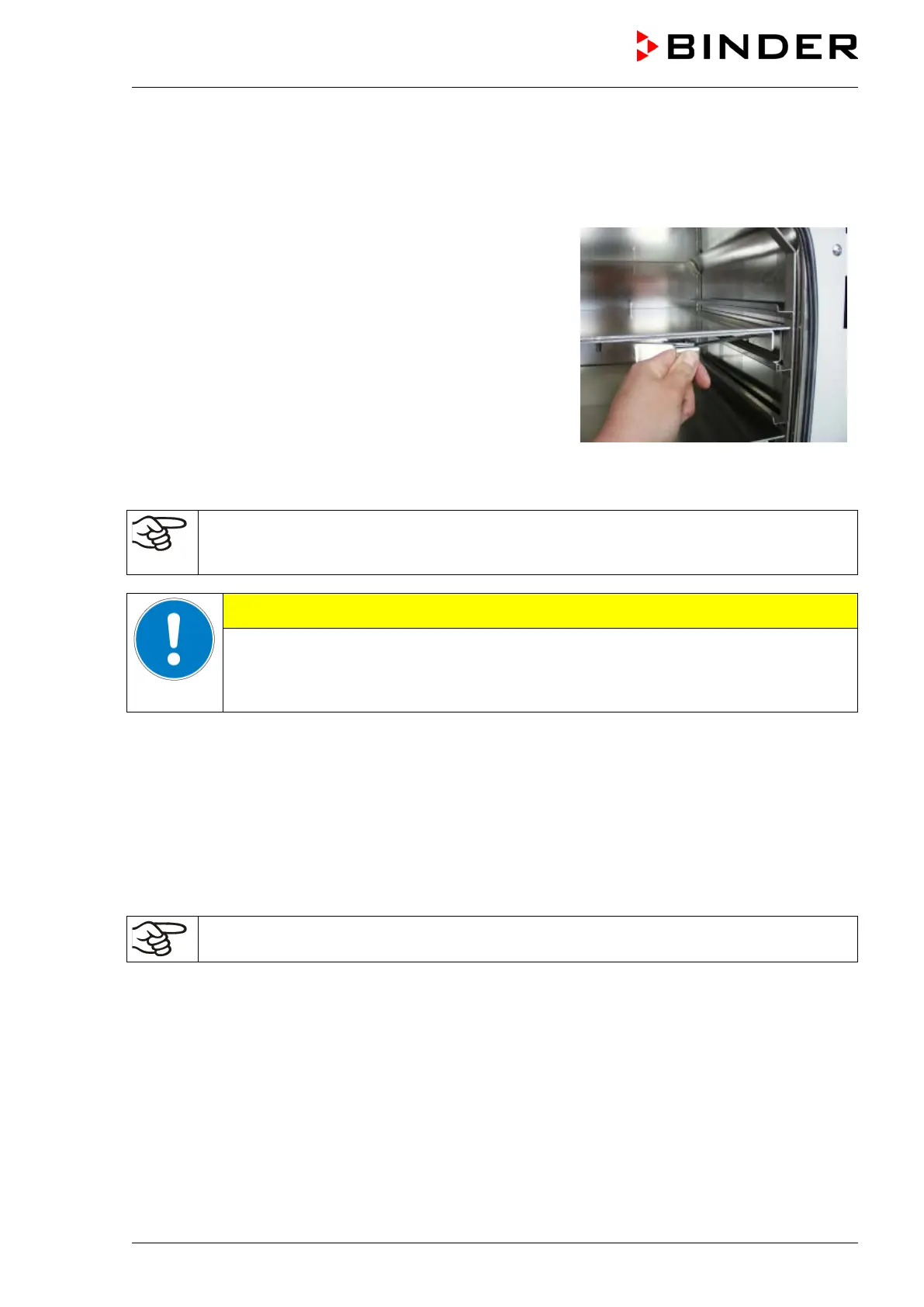
Figure 7: Using the expansion racks
• Pushing the locking lever: The expansion rack is released and can be removed.
• Pulling the locking lever: The expansion rack is pressed against the inner chamber walls.
Following each new tightening of an expansion rack, check that the lateral parts of the rack fit
closely over their whole surface to the inner chamber wall. This is necessary in order to
ensure the specified temperature exactitude.
Invalid calibration.
∅ Do NOT change between aluminum and stainless steel racks
Use the delivered expansion racks only
4.2 Vacuum connection
Always connect the VD vacuum drying oven to a vacuum pump or to a domestic vacuum system. For this
purpose, the vacuum connection (13) with small flange DN16 must be connected to the back of the
chamber at the top with the vacuum pump or domestic vacuum system via a vacuum suction hose. For
connecting to the chamber, BINDER recommends the connection kit VD, Art. no. 8012-0146.
With the option “stainless steel tubing” between the vacuum oven and vacuum module, the vacuum
connection is already located inside the vacuum module.
Vacuum pumps with a suction capacity of 1-30 m³/h are suitable for the VD vacuum drying
oven. Permissible end vacuum: 10
-2
mbar / 0.0003 inHg.
4.3 Inert gas connection
When operating the VD vacuum drying oven with inert gas, correctly follow the technical ventilation
measures, as described in the DGUV guidelines 213-850 on safe working in laboratories (formerly
BGI/GUV-I 850-0, BGR/GUV-R 120 or ZH 1/119, issued by the employers’ liability insurance association)
(for Germany).
Connect the inert gas supply to the inert gas connection (adapter with hose olive diameter 8 mm / 0.31 in)
via a pressure reducer. Screw the enclosed adapter with hose olive on the thread (12) at the chamber
rear. Set the pressure reducer to a pressure slightly above ambient pressure. Ensure that the pressure
reducer will certainly open. Do not alter this setting in order to avoid perturbation inside the oven and
release of big quantities of inert gas after flooding the VD.