VD (E2.1) 07/2017 page 56/96
15. Switching contacts 24V DC via operation lines
Operation lines 1 and 2 are used to switch on and off electrical equipment (nominal voltage 24 V DC,
current consumption max. 0.4 A). The switching contacts are connected with two DIN sockets (13) and
(14) at the chamber rear.
The operation lines permit switching on and off the switching contacts by program control. You can
program the operation lines in “Fixed value entry mode” (chap. 6) as well as in the “Program editor”
(chap. 8.2) via the operation lines (switching state “0” = Off, switching state “1” = On).
Set the positions “100” or “010” or “110” or “000” as follows:
Operation line 3
(no function)
Operation lines 1 and 2 ON
You can combine any of the switching states of the operation lines. You can recognize switching state
ON when the LED (7b) for operation line 1 and the LED (7c) for operation line 2 light up.
Operation lines 1 and 2 are designed for the following options:
• Operation line 1: Program controlled evacuation (option “vacuum module with pump”, see chap. 16.3)
• Operation line 2: Program controlled venting (option “program controlled venting”, available via
BINDER INDIVIDUAL customized solutions)
You can connect any other device or electrical equipment with a nominal tension of 24 V DC and a
current consumption of max. 0.4 A.
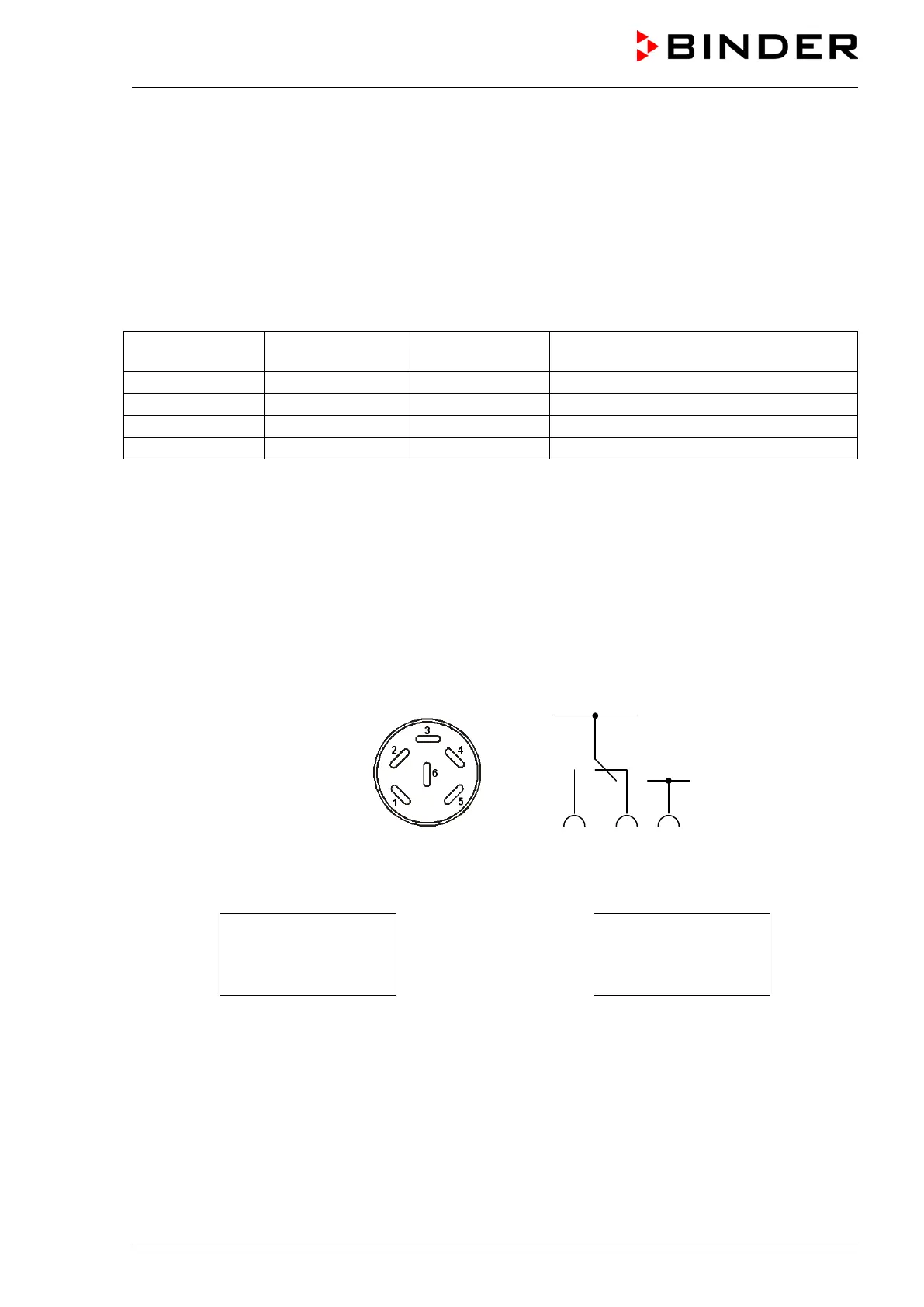
Establish the connection via the DIN sockets at the rear of the oven:
Figure 13: Pin configuration of the DIN sockets (15) and (16)
OPERATION LINE 2
OUTPUT
24V DC / MAX. 0,4A
OPERATION LINE 1
OUTPUT
24V DC / MAX. 0,4A
Figure 14: Legend at the DIN socket (15) Figure 15: Legend at the DIN socket (16)
A suitable DIN plug is enclosed.