Chapter1 Motherboard Description
1-17
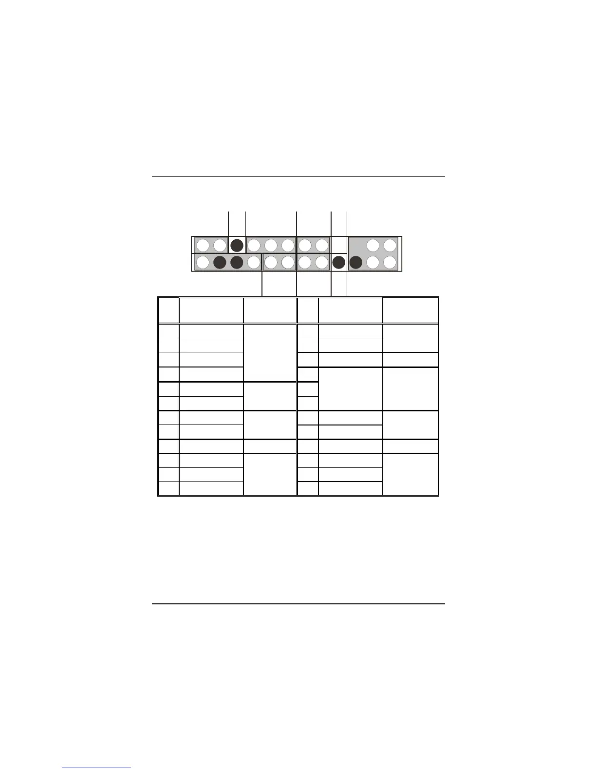
1.6.1 Front Panel Connector: JPANEL1
Pin Assignment Function Pin Assignment Function
No.
No.
1
+5V
2
Sleep Control Sleep
3
NA
4
Ground Button
5
NA
6
NA
NA
7
Speaker
Speaker
Connector
8
Power LED (+)
9
HDD LED (+)
10
Power LED (+)
11
HDD LED (-)
Hard Disk
LED
12
Power LED (-)
POWER
LED
13
Ground
14
Power Button Power-on
15
Reset Control
Reset
Button
16
Ground Button
17
NA
18
KEY
19
NA
20
KEY
21
VCC5
22
Ground
23
IRTX
IrDA
Connector
24
IRRX
IrDA
Connector
Speaker Connector
An offboard speaker can be installed on the motherboard as a manufacturing option.
An offboard speaker can be connected to the motherboard at the front panel connector.
The speaker (onboard or offboard) provides error beep code information during the
Power On Self-Test when the computer cannot use the video interface. The speaker is
not connected to the audio subsystem and does not receive output from the audio
subsystem.
SPEAKER
POW-LED
ON/OFF
K
E
Y
HDLED
IRDA
SLP
(-)(+)
(-)(+) (+)
NARST
2
1
24
23
NA
IRDA