23
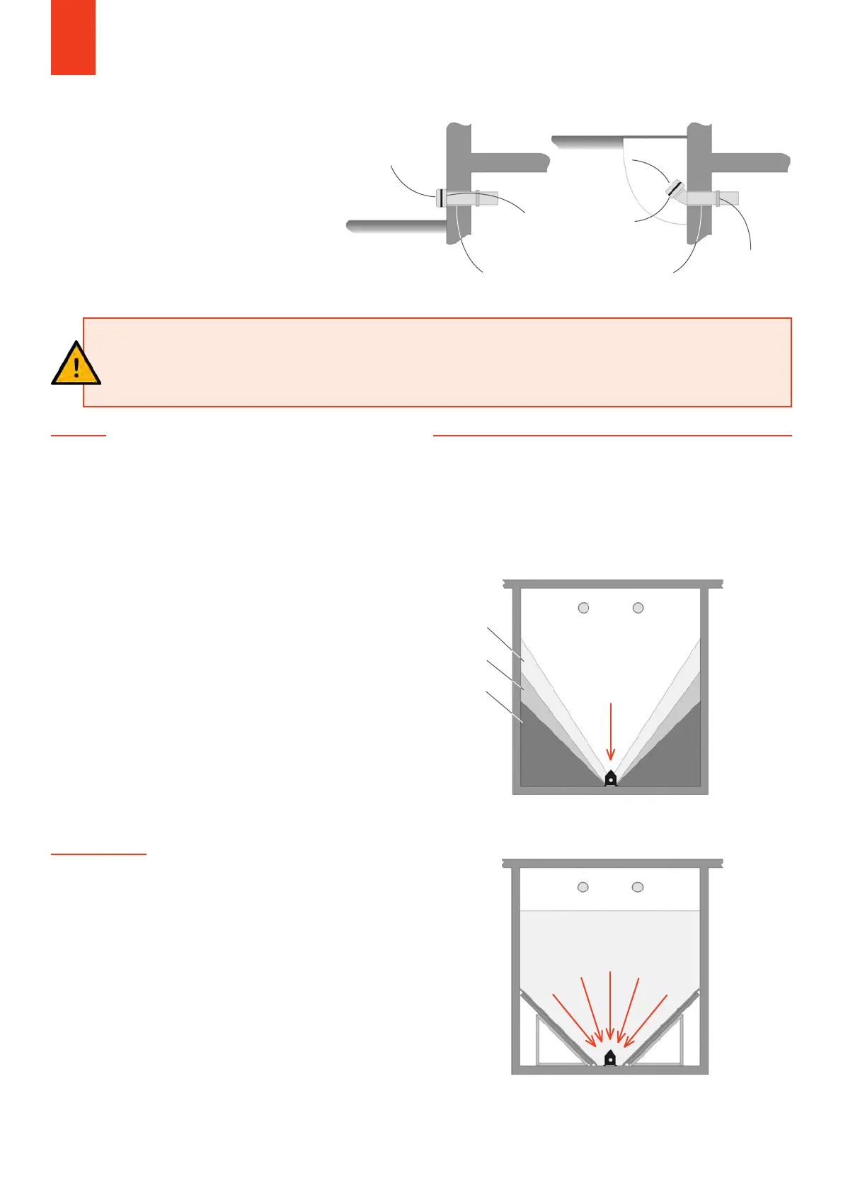
WITHOUT LIGHT SHAFT WITH LIGHT SHAFT
Closing lid
Coupling spigot
NW 100 (Storz Type A)
Mount filling couplings firmly
in the storage room wall
Closing lid
Earthing
clamp
FILLING SYSTEM
Two „filling nozzles“ are required to fill a
pellet store. An extraction fan is connected
to one filling nozzle when the fuel is
delivered and the pellets are blown in at the
other. A wall opening with a diameter of 125-
150 mm must be made on site. The filling
couplings are firmly installed in this opening
with suitable material (they must not loosen
when filling the store). The permissibility of
installation foam must be clarified in advance
with the pellet supplier.
PLANING FOLDER PELLET BOILER
GENERAL NOTES
• Only metal pipes or earthed plastic pipes may be used for
the filling system.
• The filling system must be earthed against electrostatic
charges.
• The filling pipes or filling lines used must be smooth-
walled throughout on the inside, any necessary
extensions of the pipes via sleeves.
• When welding pipes, there must be no burrs or weld
seams protruding on the inside.
• The filling system must not end with a bend, but a
straight pipe section of at least 500 mm must follow after
a bend as a calming section.
NOT TO BE USED:
• Pipes made of plastic (danger of electrostatic charges).
• Pipes that can destroy the pellets during the filling process
due to their nature (e.g. spiral ducts from ventilation
technology).
ATTENTION!
The filling couplings must be firmly connected to the masonry. Earthing via the equipotential bonding is neces-
sary to prevent electrostatic charges during the filling process! The impact protection mat must be mounted in
such a way that the injection nozzle is opposite! Minimum distance between the filling couplings: min. 0.5 m!
6.6 NOTES ON THE EXECUTION
OF THE FILLING SYSTEM
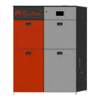
6.7 SLOPING FLOOR
The storage room must be designed with sloping floors so
that it can be almost completely emptied via the extraction
system used (e.g. screw discharge, probe discharge).
GENERAL NOTES:
• The angle of the sloping floor must be 45° so that the
pellets slide down automatically.
• The slanted floor should preferably be made of derived
timber products with a surface that is as smooth as
possible (e.g. chipboard or coated chipboard. OSB
boards tend to have a rough surface).
• The sloping floor must be able to withstand the static
requirements of the weight load from the pellets (density
650 kg/m³).
• Suitable angle beams are available for the substructure,
which facilitate the assembly of the sloping floor.
• The sloping floor should be made tight enough to the
connection to the storage room walls so that no pellets
can trickle into the empty space (these cannot be
removed from there).
• The sloping floor must not reduce the lateral openings
between the conveyor channel and the cover during
screw discharge.
WITHOUT SLOPING BOTTOM
- Increasing slope angle
WITH SLOPING BOTTOM 45°
- Almost complete emptying
depending on pellet quality
- Constant slope angle
1. Filling
2. Filling
3. Filling