6
PLANING FOLDER PELLET BOILER
• Safety and monitoring devices must not be removed,
bypassed or otherwise rendered inoperative. Use a dust
mask during cleaning and ash disposal to avoid health
hazards and damage.
• Electrical connection: 230 V, 50 Hz; fuse protection 16 A,
tripping behaviour slow. Protective measure Zeroing with
Fi circuit breaker ( voltage limits according to EN-50160)
ATTENTION: ISO standard 60364 must be observed!
Operating limits: Max. Ambient temperature 0-45°C;
max. humidity 0-95 %.
• There must be an emergency heating switch (all poles
and all sides can be switched o) in front of the boiler
room! Switch it o before carrying out maintenance and
/ or service work!
• The heating system may only be installed and operated
in properly designed heating or installation rooms and
is not designed for outdoor use, nor may it be operated
if it is exposed to external influences of water (dripping,
splashing and jetting water).
• The combustion air in the heating or installation
room must be free of halogenated hydrocarbons (e.g.
contained in spray cans, solvents and cleaning agents,
paints, adhesives). The installation of a washing machine
and/or tumble dryer is also not permitted, otherwise the
guarantee / warranty will expire.
• A suitable vent valve must be fitted at the top of the boiler.
• The boiler must be filled with heating water according to
VDI 2035 or Ö-Norm H 5195-1.
• When connecting the pellets boiler to the water supply
or to the heating circuit, the pellets boiler must be
secured against excessive water pressure by means of
an appropriate safety device on the system side (e.g.
overpressure valve). According to the country-specific
regulations, a water shortage protection must be provided.
• When connecting the pellet boiler to the water supply,
an appropriate safety device on the system side must
ensure that non-potable water is prevented from being
sucked back into the water supply system.
• The fire protection regulations must be implemented on
site in accordance with the applicable ocial regulations!
A moisture-resistant (FU) chimney (material 1.4401 or 1.4404
recommended) with a maximum flue draught of 10 Pa (0.10
mbar) is required. The connecting pipe (flue gas pipe) must
be laid with a minimum gradient of 10° (30-45° is optimal)
with a maximum length of 3.0 metres. The flue pipe must
be insulated with at least 25 mm. If possible, make the flue
connection with 45° bends. A connection with 90° bends can
cause flue gas problems. The flue pipe must be connected
to the chimney in such a way that no condensation water
can flow into the boiler. The boiler and the chimney must be
matched to each other (see chimney recommendation). EN
13384-1 must be used as a calculation aid.
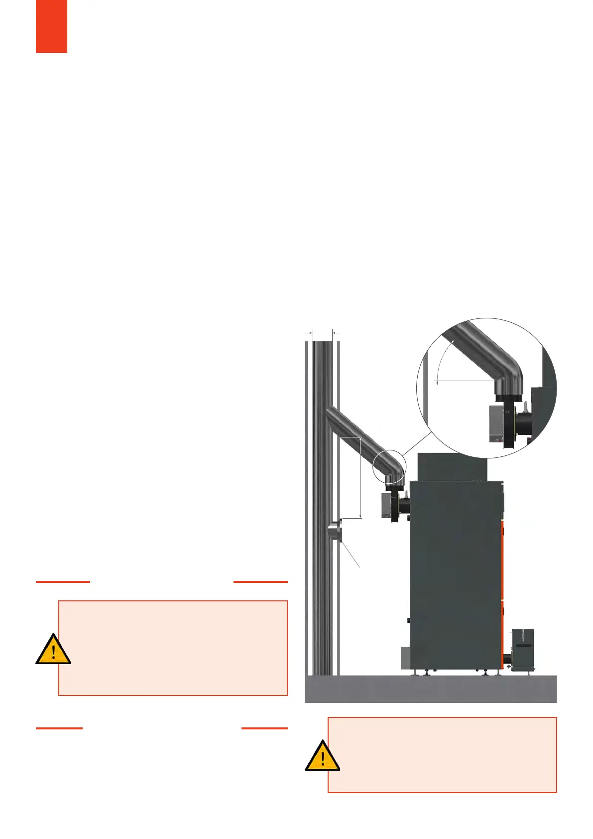
REQUIREMENTS FOR THE FLUE PIPE
• Connect the flue pipe to the chimney at an angle of at
least 10°, ideally 30 to 45°.
• The exhaust pipe must not be reduced, the diameter of
the exhaust pipe must correspond to that of the exhaust
connection.
• The flue pipe must be pressure-tight and fitted with thermal
insulation at least 25 mm thick over its entire length.
• The draught regulator must be installed at least 600 mm
below the flue pipe inlet in the flue system.
ATTENTON!
The chimney must be insensitive to moisture
(FU)! The installation of a draught regulator is
required. A chimney calculation according to
standard EN 13384-1 is required (See page 7 & 8)!
2. RETURN FLOW BOOST
3. CHIMNEY SPECIFICATION
ACHTUNG!
It must be ensured that the return
temperature does not fall below 55°C under
any circumstances. Since this cannot be
guaranteed without an automatic return flow
increase, it is mandatory to install one! Failure
to comply will invalidate the warranty.
Ø 130-140 mm
Chimney
regulator
600 mm
≥ 10° (30-45°)
All dimensions in mm!