Page 16
724-746-5500 | blackbox.com
Chapter 1: Specifications
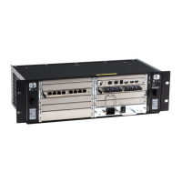
Table 1-9. DB9 (serial) connector.
Picture Pin Signal Color Signal
9 Not connected 4 DTR
8 CTS 3 TxD
7 RTS 2 RxD
6 DSR 1 Not connected
5 GND — —
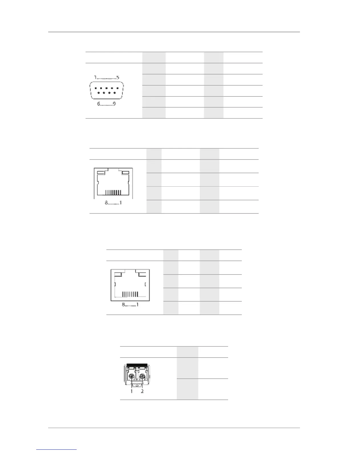
Table 1-10. RJ-45 connector.
Picture Pin Signal Color Signal
1 D1+ 5 Not connected
2 D1- 6 D2-
3 D2+ 7 Not connected
4 Not connected 8 Not connected
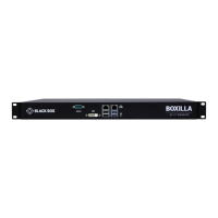
1.3.2 I/O Board CATx
Table 1-11. RJ-45 CATx connector.
Picture Pin Signal Color Signal
1 D1+ 5 D3-
2 D1- 6 D2-
3 D2+ 7 D4+
4 D3+ 8 D4-
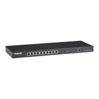
1.3.3 I/O Board SFP
Table 1-12. LC fiber connector.
Picture Diode Signal
1 Data OUT
2 Data IN