ACM200 USER MANUAL
07contact support@blustream.co.uk / support@blustream.com.au
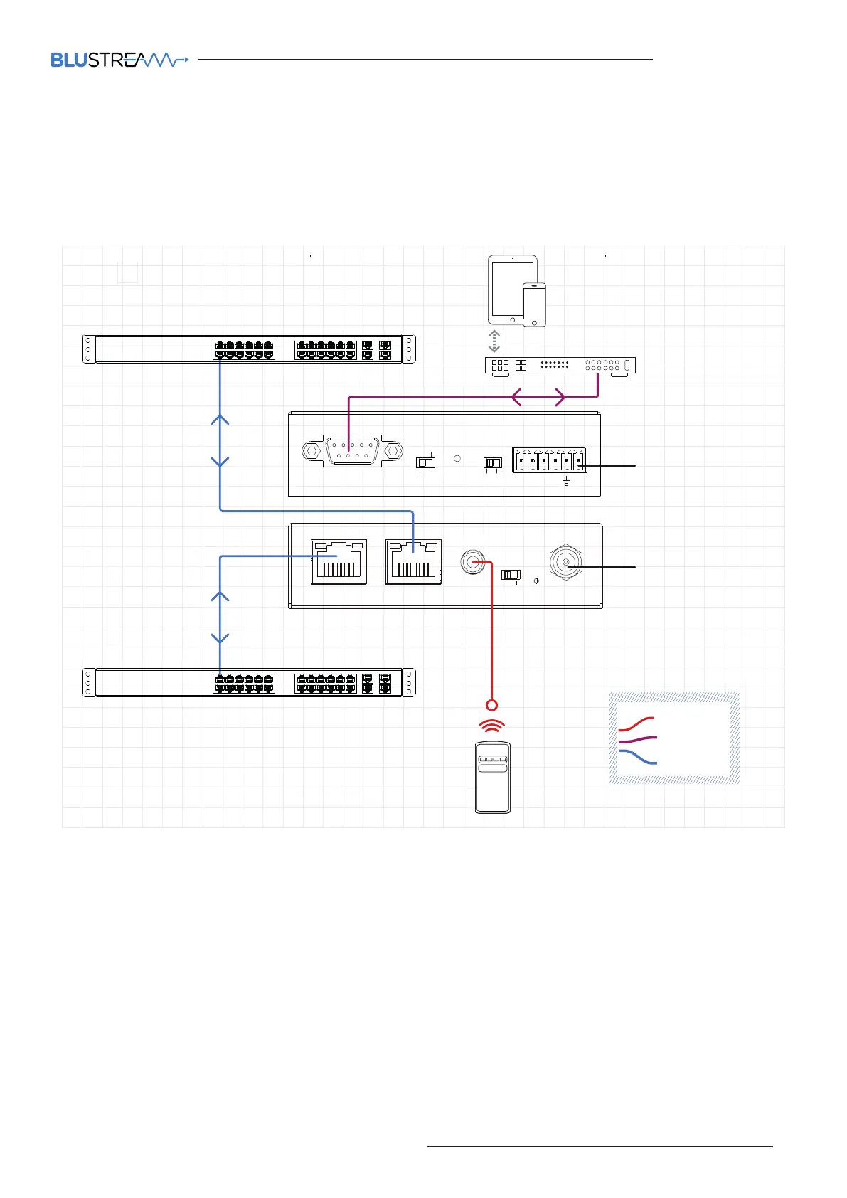
ACM200 Network Connection
The ACM200 acts as a bridge between the control network and video network to ensure that the data travelling
between the two networks are not mixed. The ACM200 must be connected via CAT cable up to 100m in length in
accordance with typical networking requirements.
Example Schematic
EX40B-Kit
RS-232
LAN Cable
IR Cable
Example Schematic
ACM200
IO Level
Reset
VOut
IO4
IO3
IO2
IO1
5V Normal
RS-232
MCU
12V
ACM200
Video LAN(PoE)
Control LAN
IR Ctrl
IR
5V
12V
DC 12V
Power
Link Link
PoE
Yellow Green Yellow Green
Reserved for future update
Control Processor
Optional 12V PSU
where no PoE is available
Multicast UHD
Network Switch
Customer Home / Business
Network Switch
1G Managed Network Switch
1G Managed Network Switch
Example Schematic
EX40B-Kit
RS-232
LAN Cable
IR Cable
Example Schematic
ACM200
IO Level
Reset
VOut
IO4
IO3
IO2
IO1
5V Normal
RS-232
MCU
12V
ACM200
Video LAN(PoE)
Control LAN
IR Ctrl
IR
5V
12V
DC 12V
Power
Link Link
PoE
Yellow Green Yellow Green
Reserved for future update
Control Processor
Optional 12V PSU
where no PoE is available
Multicast UHD
Network Switch
Customer Home / Business
Network Switch
1G Managed Network Switch
1G Managed Network Switch