14 en | System Layout Access Easy Controller 2.1
2018.11 | 1.0.6 | F.01U.122.796 Hardware Installation Manual Robert Bosch (SEA) Pte Ltd
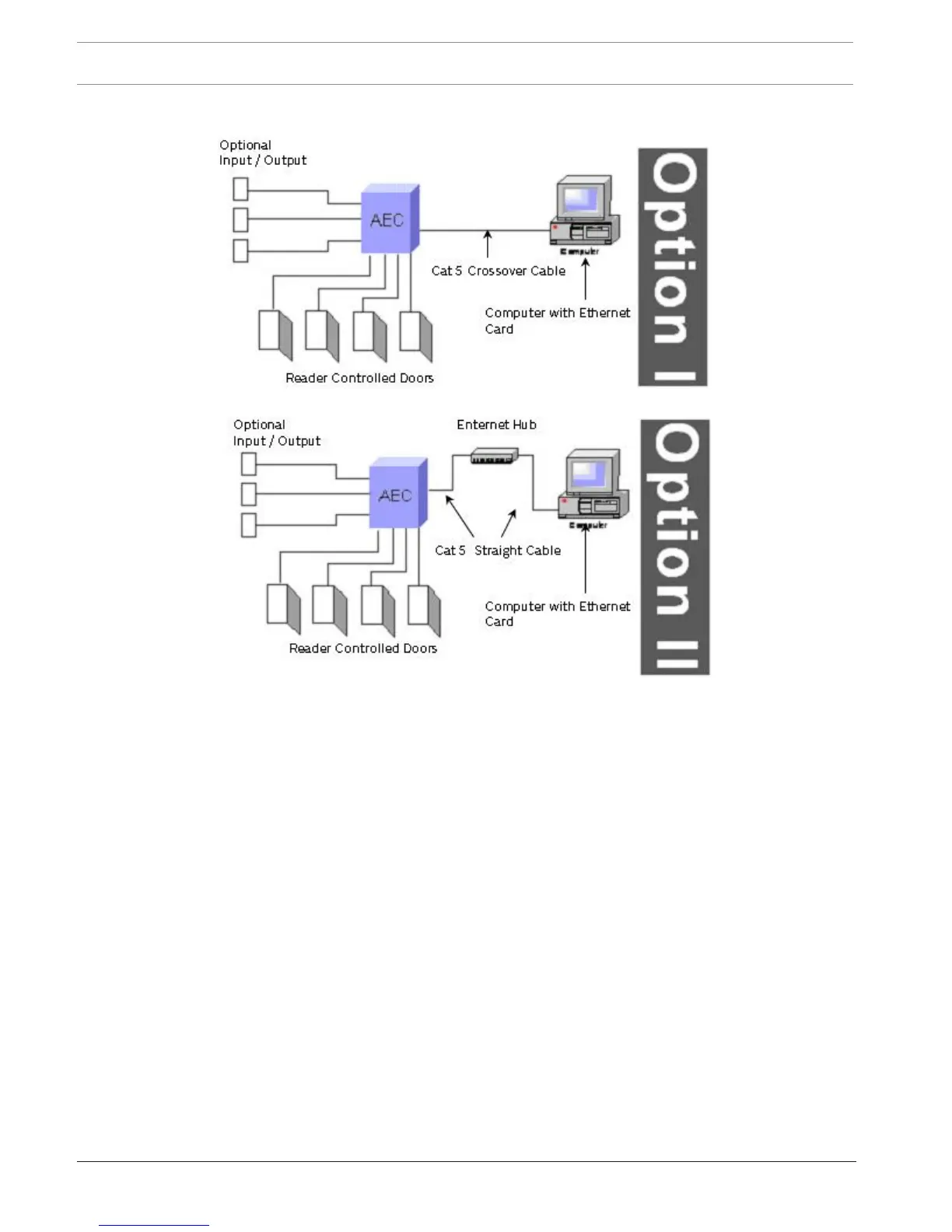
4 System Layout
Figure4.1: System Layout
Each AEC2.1 system can support up to a maximum of 16 interface boards (eight 4-Reader
boards and eight 8-IO boards). This configuration allows the system to support up to 32
Wiegand readers, 64 alarm type inputs and 64 controllable output points. System
configurations may vary, based on the requirement of the customer.
Note: UL listed panic hardware shall be used for the applications.
The figure below shows a basic configuration of the AEC2.1 system (including the converter
and additional four 4-Reader boards and four 8-IO boards).
Figure 3.2 shows the basic configuration of AEC2.1 system with additional four 4 -Reader
boards and four 8-IO boards using a converter. The converter UDS1100 can be linked to
AEC2.1’s CPU LAN port through an Ethernet network port to provide an additional multidrop
communication channel upgrading it to support up to a maximum of 16 interface boards (eight
4-Reader boards and eight 8-IO boards). This allows the AEC2.1 system to support up to 32
card readers, 64 alarm type input and 64 controllable output points.