108 en | Appendix C Detailed Wiring Access Easy Controller 2.1
2018.11 | 1.0.6 | F.01U.122.796 Hardware Installation Manual Robert Bosch (SEA) Pte Ltd
20 Appendix C Detailed Wiring
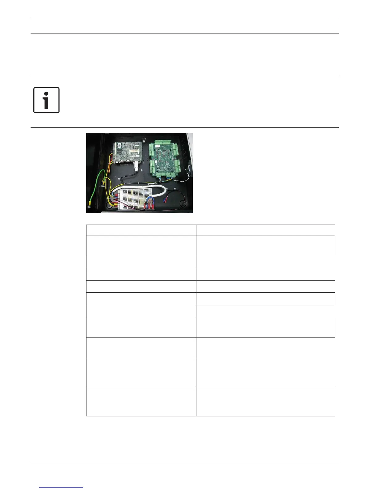
This appendix shows the detailed wiring diagram of the Main Controller Unit for the system.
The type of cable specification is tabulated below the image for quick reference.
Notice!
The image for the Main Controller only shows the general connection between itself and
other boards. Based on UL requirement, 2 different kinds of CPU board can be deployed,
however, only one type will be used in each Main Controller.
Wiring methods shall be in accordance with the National Electrical Code (ANSI/NFPA70), local
codes, and the authorities having jurisdiction
Figure20.1: Inter-connection of the components within the main controller panel
Location Cable Type
AC Input socket to PSU 0.75mm 2 x 3 (18 AWG) Core Insulated (Black)
Power Cable, Length 220mm, PVC Insulated
RJ45 to CMC, directly or via hub UTP Category 5 Cable
PSU output to CPU board 18 AWG, 4-conductors, unshielded
Back-up Battery 18 AWG, 2-conductors, unshielded
CPU to 4-Reader boards 24 AWG, 4-Conductors Data Cable, shielded
Interface boards to Interface boards RS485- 24 AWG, Cat5e, 4-conductors, shielded
Tamper Switch 24 AWG Twisted Cable Pair (2x White),
unshielded
Card Readers to interface board (4-
Reader board)
22 AWG, 6-conductors, unshielded
Input devices to input terminals of
interface boards (4-Reader and 8-IO
boards)
22 AWG, 2-conductors, unshielded
Output devises to output terminals of
interface boards (4-Reader and 8-IO
boards)
18 AWG, 2-conductors, unshielded
Note: The specification above is based on recommended minimum requirements. Shielded
cables are recommended for outdoor and/or noisy environments.
UL listed and/or recognized wire must be used for cabling and wire suitable for the
application.