Access Easy Controller 2.1 System Layout | en 15
Robert Bosch (SEA) Pte Ltd Hardware Installation Manual 2018.11 | 1.0.6 | F.01U.122.796
PSU
Backup
Battery
CPU
4-Reader
Board
PSU
Backup
Battery
4 Reader
Board
4 Reader
Board
PSU
Backup
Battery
8 IO Board4 Reader
Board
PSU
Backup
Battery
4 Reader
Board
4 Reader
Board
PSU
Backup
Battery
4 Reader
Board
RS232
RS485
RS485
RS485
RS485
Main Controller
AEC Ext
AEC Ext
AEC Ext
AEC Ext
PSU
Backup
Battery
8 IO Board
8 IO Board
RS485
AEC Ext
PSU
Backup
Battery
8 IO Board
RS485
AEC Ext
PSU
Backup
Battery
RS485
RS485
AEC Ext
PSU
Backup
Battery
AEC Ext
4 Reader
Board
Converter
8 IO Board
8 IO Board
8 IO Board
8 IO Board
LAN Port
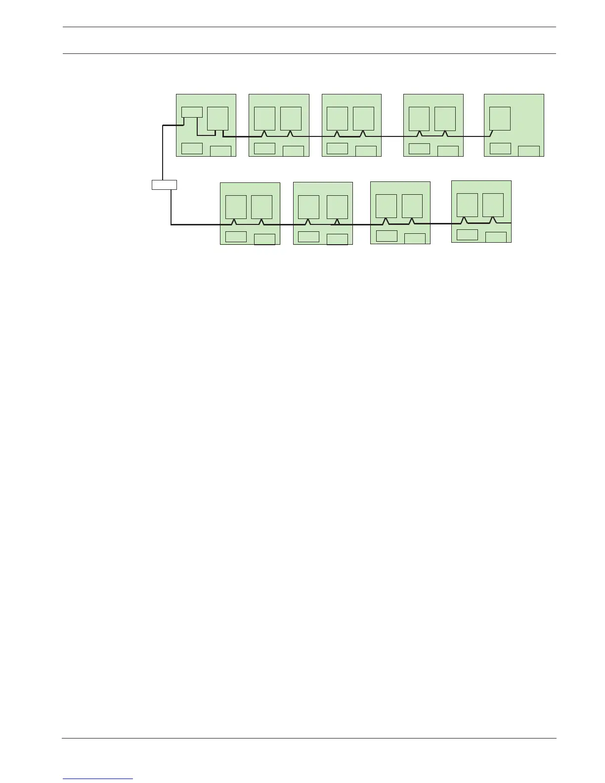
8* 4-Reader Board = 32 Readers (64 programmed Inputs and Outputs)
8* 8 Input/Output board = 64 Inputs & Outputs (free programmable I/O)
Each RS 485 loop can support upto 4*4 reader board and 4*8Input/Output board
RS485
Figure4.2: Basic Configuration of AEC2.1 system
4.1 System Specifications
Dimensions
Enclosure (H x W x D) : 400mm x 400mm x 94mm
Controller
CPU : 32 bits Microprocessor 500 MHz or higher
Memory : 128 MB RAM or higher
Storage : Compact Flash 256 MB and above
Data Integrity : Encryption used for user ID and PIN
Power Requirements
Primary Voltage Input (AC) : 100~240 VAC
Secondary Voltage Input : +5 VDC for CPU board
+13.6 +/-0.1 VDC for 4-Reader and 8-IO boards
Backup Battery : 12 VDC, 7 AH rechargable battery
(Optional: Not included in standard package)
Interface Boards :
4-Reader Board 8-IO Board
Voltage Requirement : +13.6 +/-0.1 VDC from PSU +13.6 +/-0.1 VDC from PSU
Number of Wiegand Readers
Supported
: 4 -