34 en | 8-Input-Output Board Access Easy Controller 2.1
2018.11 | 1.0.6 | F.01U.122.796 Hardware Installation Manual Robert Bosch (SEA) Pte Ltd
There are two terminals for each input point. Each input point is supervised and must be
terminated according to the type of supervision applied to that particular input (Refer to
Wiring Diagram for Supervised Inputs, page 57). All unused points should have the termination
resistor installed across the terminals within the controller. Refer to 4-Reader Board, page 23
for detailed wiring diagrams.
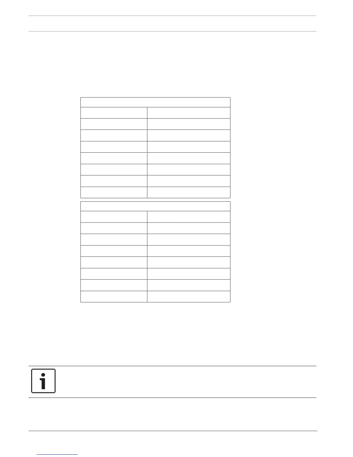
The charts below show the various termination points on the terminal strips.
T6 Terminal Strip
IN1 Input Point #1
GND Input Point #1
IN2 Input Point #2
GND Input Point #2
IN3 Input Point #3
GND Input Point #3
IN4 Input Point #4
GND Input Point #4
T7 Terminal Strip
IN5 Input Point #5
GND Input Point #5
IN6 Input Point #6
GND Input Point #6
IN7 Input Point #7
GND Input Point #7
IN8 Input Point #8
GND Input Point #8
7.1.3 Output Connectors
Four 6-pin terminal strips provide connection points for connection of external devices
controlled by the AEC2.1. The terminal strips are labelled on the circuit board as T2, T3, T4
and T5. The output terminals are Form-C type dry contacts from relays located on the 8-IO
board. For each relay, Normally Closed (N/C), Normally Open (N/O) and a Common terminal
(COM) are provided.
Notice!
The contacts of all relays are rated at DC 24V/1A maximum