Access Easy Controller 2.1 8-Input-Output Board | en 35
Robert Bosch (SEA) Pte Ltd Hardware Installation Manual 2018.11 | 1.0.6 | F.01U.122.796
The relay contacts can be connected directly to many low voltages DC powered devices,
including alarm bells, security lights, horns, etc. When using the outputs to control high
voltage devices, such as lighting circuits, electric door controllers, gate motors, etc., an
external interface relay must always be used. Also, use an external relay when interfacing with
AC-power devices.
In all instances where the output relay is used to operate an inductive load, such as when
interfacing with an external relay, or powering the coil of an alarm bell, a back-biased diode
should be wired across the coil of the driven device. This will protect the electronic circuitry
on the 8-IO board by providing suppression from back-emf when the devices are deactivated.
Each output relay on the 8-IO board also has a corresponding LED which lights up whenever
the relay is activated.
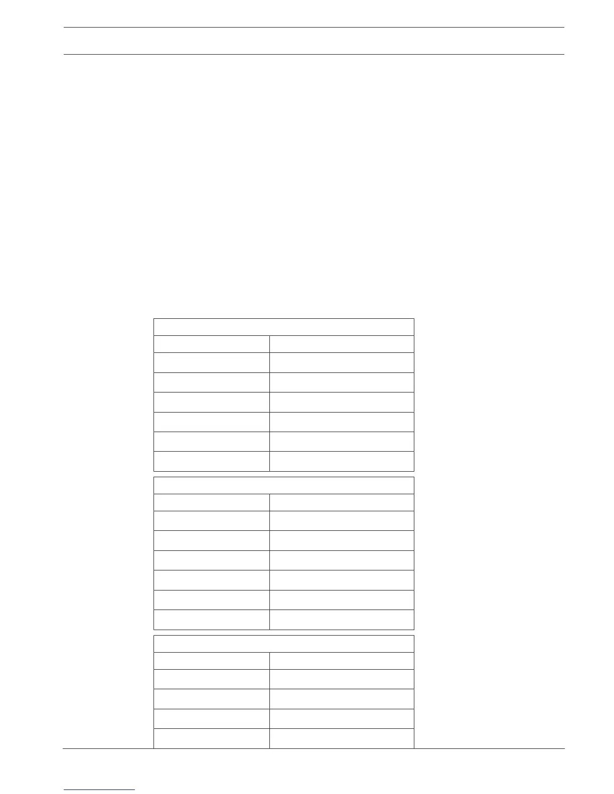
Beginning from the top of the 8-IO board, T2 provides connection points for outputs 1 and 2.
T3 provides connection points for outputs 3 and 4. T4 provides connection points for outputs
5 and 6. T5 provides connection points for outputs 7 and 8. The pin configuration for each
output connector is shown in the tables below.
T2 Terminal Strip (top connector)
Pin# Function
1 Output #1 (common)
2 Output #1 (normally closed)
3 Output #1 (normally open)
4 Output #2 (common)
5 Output #2 (normally closed)
6 Output #2 (normally open)
T3 Terminal Strip (second connector from top)
Pin# Function
1 Output #3 (common)
2 Output #3 (normally closed)
3 Output #3 (normally open)
4 Output #4 (common)
5 Output #4 (normally closed)
6 Output #4 (normally open)
T4 Terminal Strip (third connector from top)
Pin# Function
1 Output #5 (common)
2 Output #5 (normally closed)
3 Output #5 (normally open)
4 Output #6 (common)