Access Easy Controller 2.1 The CPU Board | en 21
Robert Bosch (SEA) Pte Ltd Hardware Installation Manual 2018.11 | 1.0.6 | F.01U.122.796
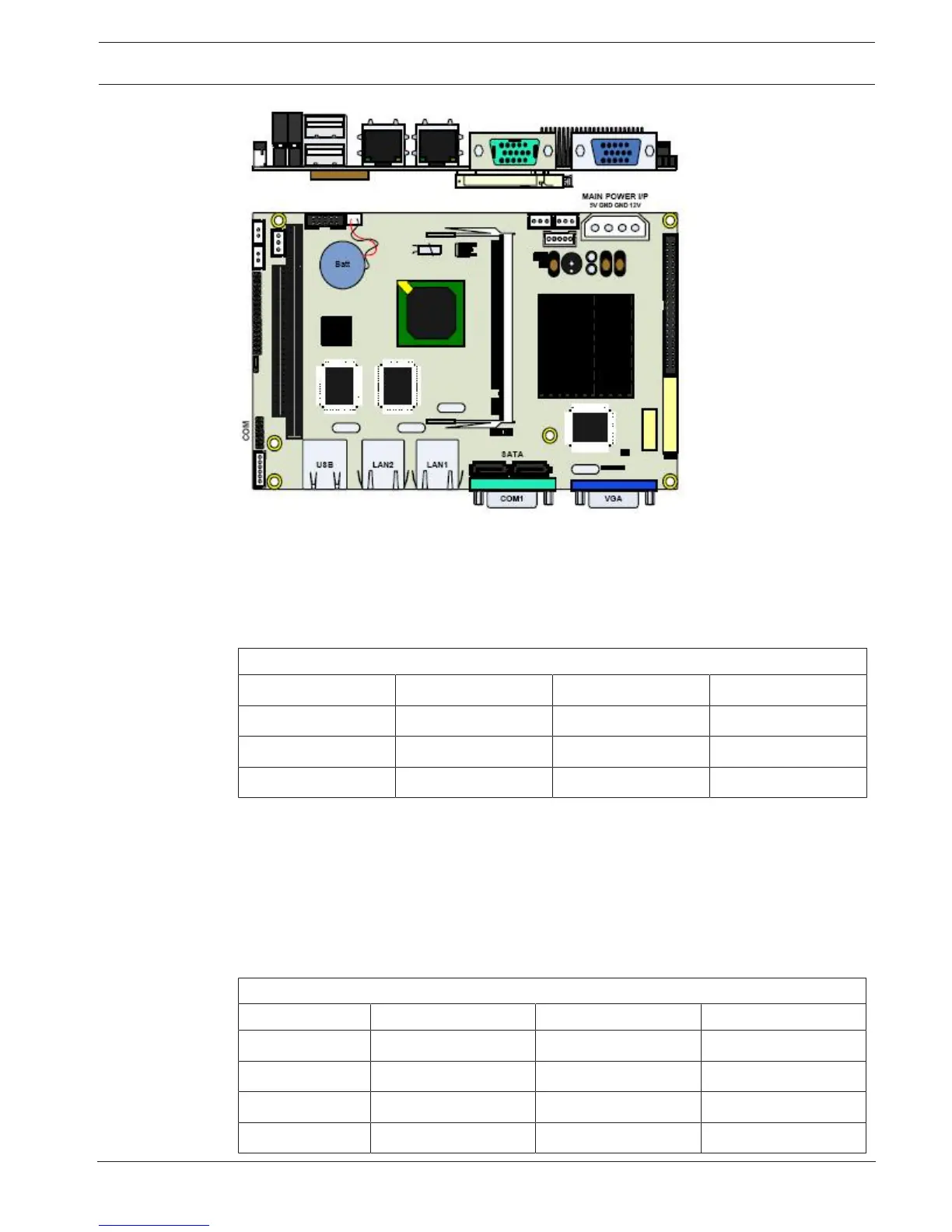
Figure5.4: Type3 CPU Board
Ethernet Connector
A Category 5 cable is connected from this RJ45 socket to the plug-in 100BaseT Ethernet card
located in the Central Monitoring Computer directly or via a hub. The table below shows the
pin configuration for the socket.
100Base-Tx Ethernet connector
1 Tx+ 2 Tx-
3 Rx+ 4 NC
5 NC 6 Rx-
7 NC 8 NC
Serial Port for Modem
This is a standard RS232 communication port used for modem connection. Refer to cable
connection for more details.
Serial Port for the interface board
This is a 9 pins serial port. The serial port is connected to the interface boards.
RS232 Serial Port
Pin Signal Pin Signal
1 DCDB 2 RXDB
3 TXDB 4 DTRB
5 GND 6 DSRB
7 RTSB 8 CTSB