Access Easy Controller 2.1 4-Reader Board | en 27
Robert Bosch (SEA) Pte Ltd Hardware Installation Manual 2018.11 | 1.0.6 | F.01U.122.796
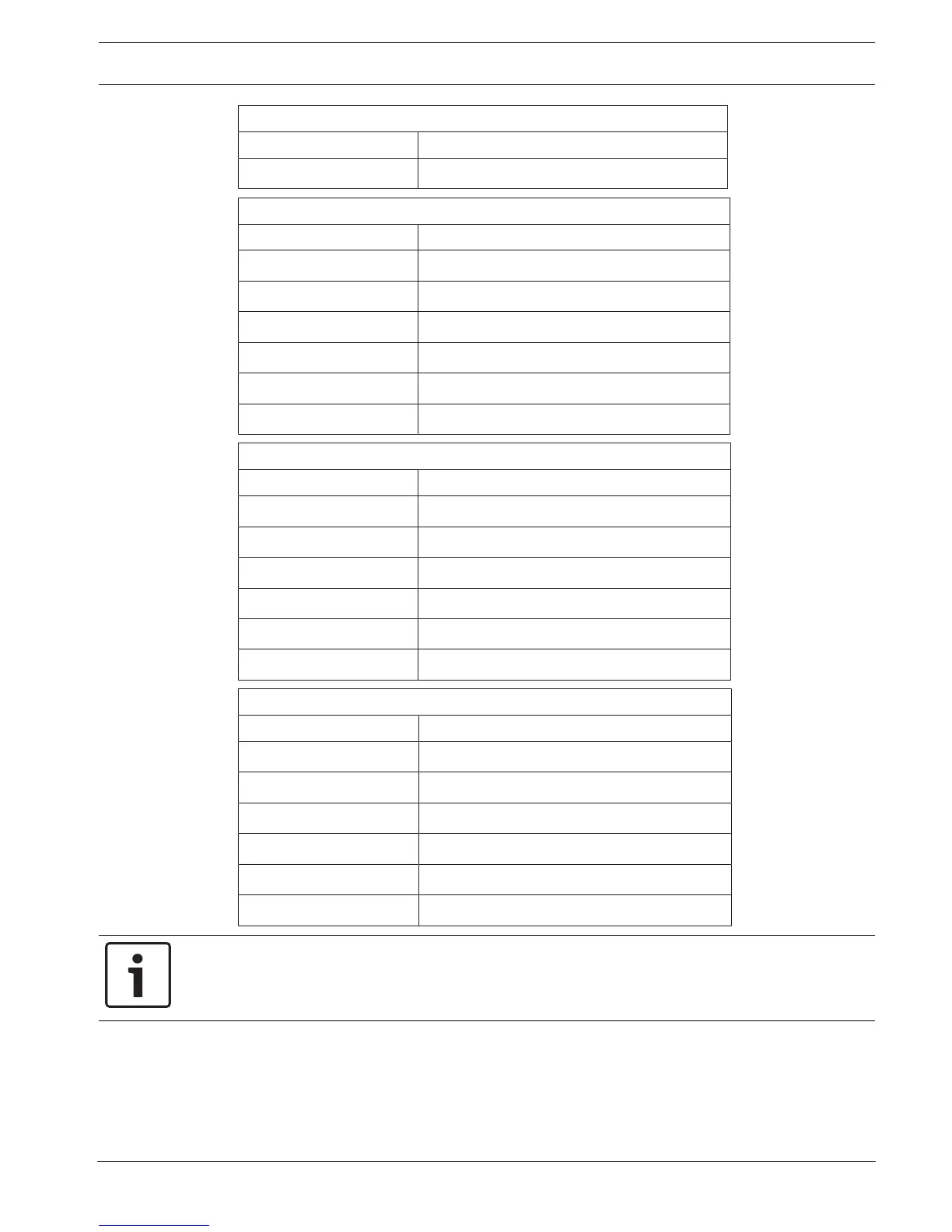
T2 Terminal Strip (top terminal)
Pin# Function
6 Reader #2 (normally open)
T3 Terminal Strip (second terminal from top)
Pin# Function
1 Reader #3 (common)
2 Reader #3 (Normally closed)
3 Reader #3 (normally open)
4 Reader #4 (common)
5 Reader #4 (normally closed)
6 Reader #4 (normally open)
T4 Terminal Strip (third terminal from top)
Pin# Function
1 Spare (common)
2 Spare (Normally closed)
3 Spare (normally open)
4 Spare (common)
5 Spare (normally closed)
6 Spare (normally open)
T5 Terminal Strip (bottom terminal)
Pin# Function
1 Spare (common)
2 Spare (Normally closed)
3 Spare (normally open)
4 Common Alarm Output (common)
5 Common Alarm Output (normally closed)
6 Common Alarm Output (normally open)
Notice!
The common alarm output relay only exists on the first 4-Reader board. On boards 2, 3 and 4
this relay is an additional spare.