Access Easy Controller 2.1 How to Install the Access Easy Controller 2.1 | en 61
Robert Bosch (SEA) Pte Ltd Hardware Installation Manual 2018.11 | 1.0.6 | F.01U.122.796
Notice!
AEC2.1 uses RS485 multi-drop communication channels between the interface boards. An
end-of-line jumper is to be added on the last interface board of the configuration to stabilize
the communication.
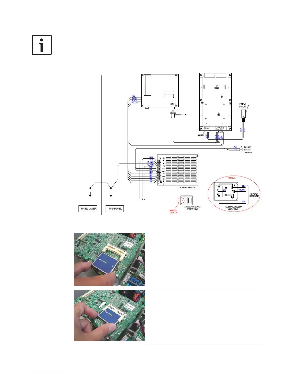
The figure below shows the inter-connection of the Main Controller panel.
Figure11.2: Inter-connection of the components within the main controller panel
Inserting Compact Flash onto the AEC2.1 CPU
1. Position the Compact Flash in the correct
orientation.
2. Slot in the Compact Flash as shown.